 |
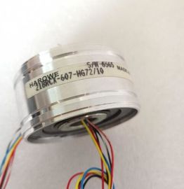
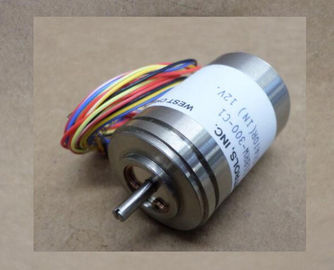
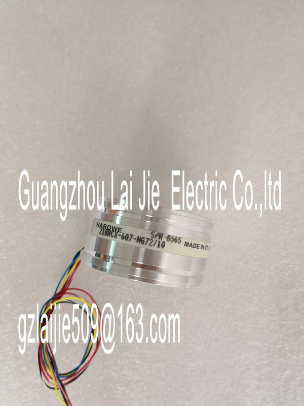
| Place of Origin: | GERMANY |
| Brand Name: | HAROWE |
| Certification: | CE |
| Model Number: | 11BRCT-300-T10A |
| Minimum Order Quantity: | 1pcs |
|---|---|
| Packaging Details: | carton |
| Delivery Time: | in stock |
| Payment Terms: | T/T, Western Union, MoneyGram |
| Supply Ability: | 100pcs/week |
| HAROWE: | HAROWE | 11BRCT-300-T10A: | 11BRCT-300-T10A |
|---|---|---|---|
| GERMANY: | GERMANY | Temperature: | 20-90 |
| Color: | Black | Dimension: | 90mm |
| Wire: | Wire | Material: | Iron |
![]()
![]()
![]()
| Enabling of the diagnostics, with missing or too little supply voltage L+. Overflow |
|
| Enabling of the diagnostics if the measured value violates the high limit. Underflow |
|
| Enabling of the diagnostics if the measured value violates the low limit. Wire breakd |
Enabling of the diagnostics if the module has no current flow or the current is too weak for
the measurement at the corresponding configured input or the applied voltage is too low.
Current limit for wire break diagnostics
Threshold for reporting wire breaks. The value can be set to 1.185 mA or 3.6 mA, depending
on the sensor used.The individual measured values are smoothed using filtering. The smoothing can be set in
4 levels.
Smoothing time = number of module cycles (k) x cycle time of the module.
The following figure shows after how many module cycles the smoothed analog value is
almost 100%, depending on the set smoothing. Is valid for each signal change at the analog
inputEnable a hardware interrupt at violation of high limit 1 or 2 or low limit 1 or 2.
Low limit 1 or 2
Specifies the low limit threshold that triggers hardware interrupt 1 or 2.
High limit 1 or 2
Specifies the high limit threshold that triggers hardware interrupt 1 or 2The module can be configured differently in STEP 7; see following table. Depending on the
configuration, additional/different addresses are assigned in the process image of the inputs.
Configuration options of AI 8xU/I HS
You can configure the module with STEP 7 (TIA Portal) or with a GSD file.
When you configure the module by means of the GSD file, the configurations are available
under different abbreviations/module names.
The following configurations are possible:The value status is always activated for the following module names:
● AI 8xU/I HS QI
● AI 8xU/I HS S QI
● AI 8xU/I HS MSI
An additional bit is assigned to each channel for the value status. The value status bit
indicates if the read in digital value is valid. (0 = value is incorrect).The following figure shows the address space allocation for the configuration as 8-channel
module. You can freely assign the start address for the module. The addresses of the
channels are derived from the start address.
"IB x" stands, for example, for the module start address input byte x.
For the configuration as a 8 x 1-channel module, the channels of the module are divided into
multiple submodules. The submodules can be assigned to different IO controllers when the
module is used in a shared device.
The number of usable submodules is dependent on the interface module used. Observe the
information in the manual for the particular interface module.
Contrary to the 1 x 8-channel module configuration, each of the eight submodules has a
freely assignable start addressThe channels 0 to 7 of the module are copied in up to four submodules with configuration 1 x
8-channel module (Module-internal shared input, MSI). Channels 0 to 7 are then available
with identical input values in different submodules. These submodules can be assigned to up
to four IO controllers when the module is used in a shared device. Each IO controller has
read access to the same channels.
The number of usable submodules is dependent on the interface module used. Please
observe the information in the manual for the particular interface module.
Value status (Quality Information, QI)
The meaning of the value status depends on the submodule on which it occurs.
For the 1st submodule (= basic submodule), the value status 0 indicates that the value is
incorrect.
For the 2nd to 4th submodule (=MSI submodule), the value status 0 indicates that the value
is incorrect or the basic submodule has not yet been configured (not ready)You can find information on the Shared Input/Output (MSI/MSO) function in the section
Module-Internal Shared Input/Output (MSI/MSO) of the PROFINET with STEP 7 V13The following figure shows the address space assignment with the configuration as
8-channel module for the oversampling function. You can freely assign the start address for