 |
| Place of Origin: | GERMANY |
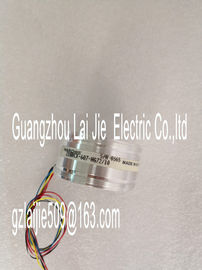
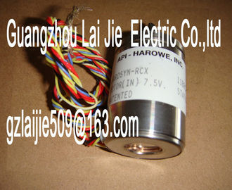
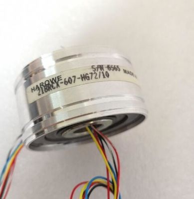
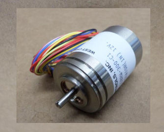
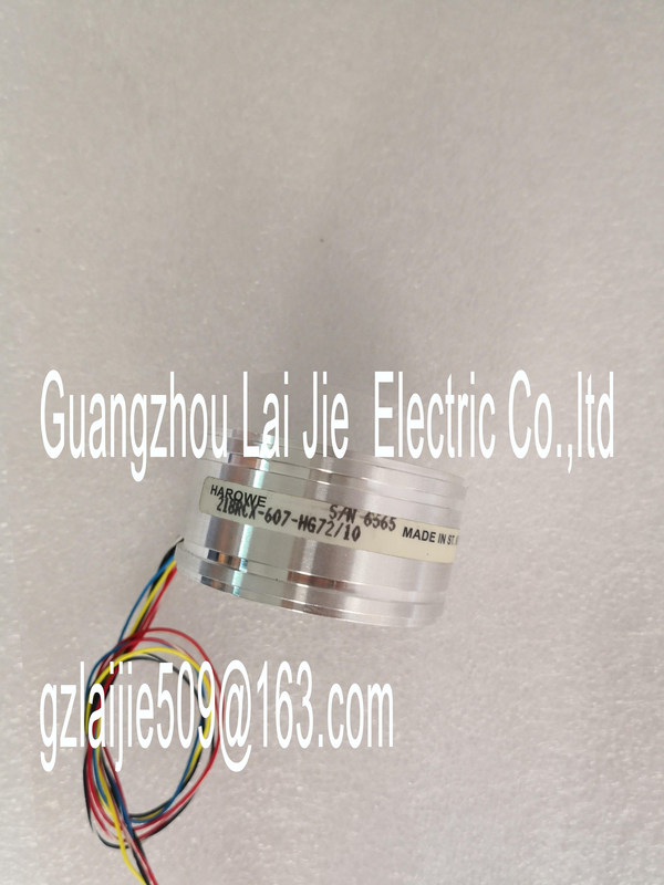
| Brand Name: | HAROWE |
| Certification: | CE |
| Model Number: | 11BRCT-300-T64A |
| Minimum Order Quantity: | 1pcs |
|---|---|
| Packaging Details: | carton |
| Delivery Time: | in stock |
| Payment Terms: | T/T, Western Union, MoneyGram |
| Supply Ability: | 100pcs/week |
| HAROWE: | HAROWE | 11BRCT-300-T64A: | 11BRCT-300-T64A |
|---|---|---|---|
| Material: | Iron | Germany: | Germany |
| Color: | Black | Temperature: | 20-90 |
| Dimension: | 90mm | Wire: | Wire |
| the module. The addresses of the channels are derived from the start address. Writing always starts from IB x. If fewer than 16 sub-cycles are set, the addresses that are |
|
| then unused are filled with 7FFFH. "IB x" stands, for example, for the module start address input byte x. The following figure shows the LED displays (status and error displays) |
|
| of AI 8xU/I HS.The following tables explain the meaning of the status and error displays. Remedial measures for diagnostic alarms can be found in section Diagnostic alarms.The module starts and |
flashes until the valid
parameter assignment is set.
---
On Off
Module is configured.
On Flashes
Indicates module errors (at least one error at
one channel, e.g., wire break).
Evaluate the diagnostics data and eliminate the
error (e.g., wire break).
Flashes Flashes
Hardware defective. Replace the moduleSupply voltage L+ to module too low or missing
Check supply voltage L+.
On
Supply voltage L+ is present and OK. ---
Channel disabled ---
On
Channel configured and OK. ---
On
Channel is configured (channel error pending).
Diagnostic alarm: e.g. wire break
Check the wiring.
Disable diagnostics.
See also
Diagnostics alarms (Page 35)Analog input module AI 8xU/I HS supports the following diagnostic and hardware interrupts.
You can find detailed information on the event in the error organization block with the
RALRM instruction (read additional interrupt info) and in the STEP 7 online help.
Diagnostic interrupt
The module generates a diagnostic interrupt at the following events:
● Missing supply voltage L+
● Wire break
● Overflow
● Underflow
● Parameter assignment error
Hardware interrupt
The module generates a hardware interrupt at the following events:
● Low limit violated 1
● High limit violated 1
● Low limit violated 2
● Violation of high limit 2
The module channel that triggered the hardware interrupt is entered in the start information
of the organization block. The diagram below shows the assignment to the bits of double
word 8 in local data.If the two high limits 1 and 2 are reached at the same time, the module always signals the
hardware interrupt for high limit 1 first. The configured value for high limit 2 is irrelevant. After
processing the hardware interrupt for high limit 1, the module triggers the hardware interrupt
for high limit 2.
The module has the same reaction when the low limits are reached at the same time. If the
two low limits 1 and 2 are reached at the same time, the module always signals the
hardware interrupt for low limit 1 first. After processing the hardware interrupt for low limit 1,
the module triggers the hardware interrupt for low limit 2.A diagnostics alarm is generated and the ERROR LED flashes on the module for each
diagnostics event. The diagnostics alarms can be read out in the diagnostics buffer of the
CPU, for example. You can evaluate the error codes with the user program.
If the module is operated distributed with PROFIBUS DP in an ET 200MP system, you have
the option to read out diagnostics data with the instruction RDREC or RD_REC using data
record 0 and 1. The structure of the data records is available on the in the "Manual
for interface module IM 155-5 DP ST (6E155-5BA00-0AB0)"Impedance of sensor circuit too high Use a different encoder type or modify
the wiring, for example, using cables
with larger cross-section
Wire break between the module and
sensor
Connect the cable
Channel not connected (open) • Disable diagnostics
• Connect the channel
Overflow 7H Measuring range violated Check the measuring range
Underflow 8H Measuring range violated Check the measuring range
Parameter assignment
error
10H • The module cannot evaluate parameters
for the channel
• Incorrect parameter assignment.
Correct the parameter assignment
Load voltage missing 11H Supply voltage L+ of the module is
missing
Connect supply voltage L+ to module/channel
Diagnostics alarms with value status (QI)
If you configure the module with value status (QI), the module always checks all errors even
if the respective diagnostics is not enabled. But the module cancels the inspection as soon
as it detects the first error, regardless if the respective diagnostics has been enabled or not.
The result may be that enabled diagnostics may not be displayed.
Example: You have enabled "Underflow" diagnostics, but the module detects the "Wire
break" diagnostics first and aborts after this error message. The "Underflow" diagnostics is
not detected.
Recommendation: To ensure that all errors can be diagnosed reliably, select all check boxes
under "Diagnostics".General information
Product type designation AI 8xU/I HS
HW functional status FS01
Firmware version V2.1.0
• FW update possible Yes
Product function
• I&M data Yes; I&M0 to I&M3
• Measuring range scalable No