 |
| Place of Origin: | GERMANY |
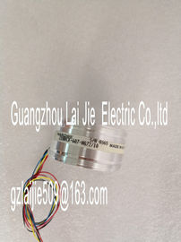
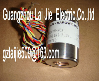
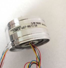
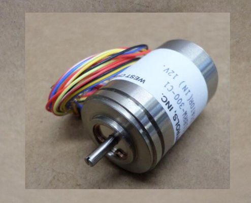
| Brand Name: | HAROWE |
| Certification: | CE |
| Model Number: | 11BRCX-300-A-20B-01 |
| Minimum Order Quantity: | 1pcs |
|---|---|
| Packaging Details: | carton |
| Delivery Time: | in stock |
| Payment Terms: | T/T, Western Union, MoneyGram |
| Supply Ability: | 100pcs/week |
| HAROWE: | HAROWE | 11BRCX-300-A-20B-01: | 11BRCX-300-A-20B-01 |
|---|---|---|---|
| GERMANY: | GERMANY | Material: | Iron |
| Color: | Black | Temperature: | 20-90 |
| Dimension: | 90mm | Wire: | Wire |
| Scalable measured values No • Adjustment of measuring range No |
|
| Engineering with • STEP 7 TIA Portal configurable/integrated as of version V14 / - |
|
| STEP 7 configurable/integrated as of version V5.5 SP3 / - • PROFIBUS as of GSD version/GSD revision V1.0 / V5.1 |
PROFINET as of GSD version/GSD revision V2.3 / -
Operating mode
• Oversampling Yes
• MSI Yes
CiR – Configuration in RUN
Reparameterization possible in RUN Yes
Calibration possible in RUN Yes
Supply voltage
Rated value (DC) 24 V
permissible range, lower limit (DC) 20.4 V
permissible range, upper limit (DC) 28.8 V
Reverse polarity protection Yes
Input current
Current consumption, max. 240 mA; with 24 V DC supply
Encoder supply
24 V encoder supply
• Short-circuit protection Yes
• Output current, max. 53 mA
Technical specifications
Analog Input Module AI 8xU/I HS (6E531-7NF10-0AB0)
Manual, 12/2016, A5E03484886-AE 37
Order number 6E531-7NF10-0AB0
Power
Power available from the backplane bus 1.15 W
Power loss
Power loss, typ. 3.4 W
Analog inputs
Number of analog inputs 8
• For current measurement 8
• For voltage measurement 8
permissible input voltage for voltage input (destruction limit), max. 28.8 V
permissible input current for current input (destruction limit), max. 40 mA
Input ranges (rated values), voltages
• 0 to +5 V No
• 0 to +10 V No
• 1 V to 5 V Yes
• Input resistance (1 V to 5 V) 50 kΩ
• -10 V to +10 V Yes
• Input resistance (-10 V to +10 V) 100 kΩ
• -2.5 V to +2.5 V No
• -25 mV to +25 mV No
• -250 mV to +250 mV No
• -5 V to +5 V Yes
• Input resistance (-5 V to +5 V) 50 kΩ
• -50 mV to +50 mV No
• -500 mV to +500 mV No
• -80 mV to +80 mV No
Input ranges (rated values), currents
• 0 to 20 mA Yes
• Input resistance (0 to 20 mA) 41 Ω; Plus approx. 42 ohms for overvoltage
protection by PTC
• -20 mA to +20 mA Yes
• Input resistance (-20 mA to +20 mA) 41 Ω; Plus approx. 42 ohms for overvoltage
protection by PTC
• 4 mA to 20 mA Yes
• Input resistance (4 mA to 20 mA) 41 Ω; Plus approx. 42 ohms for overvoltage
protection by PT• Resolution with overrange (bit including sign), max. 16 bit
• Basic execution time of the module (all channels released) 62.5 µs; independent of number of activated
channels
Smoothing of measured values
• parameterizable Yes
• Step: None Yes
• Step: low Yes
• Step: Medium Yes
• Step: Highonnection of signal encoders
• for voltage measurement Yes
• for current measurement as 2-wire transducer Yes
– Burden of 2-wire transmitter, max. 820 Ω
• for current measurement as 4-wire transducer Yes
• for resistance measurement with two-wire connection No
• for resistance measurement with three-wire connection No
• for resistance measurement with four-wire connection No
Errors/accuracies
Linearity error (relative to input range), (+/-) 0.02 %
Temperature error (relative to input range), (+/-) 0.005 %/K
Crosstalk between the inputs, max. -60 dB
Repeat accuracy in steady state at 25 °C (relative to input range), (+/-
)
0.02 %
Operational error limit in overall temperature range
• Voltage, relative to input range, (+/-) 0.3 %
• Current, relative to input range, (+/-) 0.3 %
Basic error limit (operational limit at 25 °C)
• Voltage, relative to input range, (+/-) 0.2 %
• Current, relative to input range, (+/-) 0.2 %
Interference voltage suppression for f = n x (f1 +/- 1 %), f1 = interference
frequency
• Common mode voltage, max. 10 V
Isochronous mode
Isochronous operation (application synchronized up to terminal) Yes
Filtering and processing time (TCI), min. 80 µs
Bus cycle time (TDP), min. 250 µs
Interrupts/diagnostics/status information
Diagnostics function Yes
Alarms
• Diagnostic alarm Yes
• Limit value alarm Yes; two upper and two lower limit values in
each case
Diagnostic messages