 |
| Place of Origin: | GERMANY |
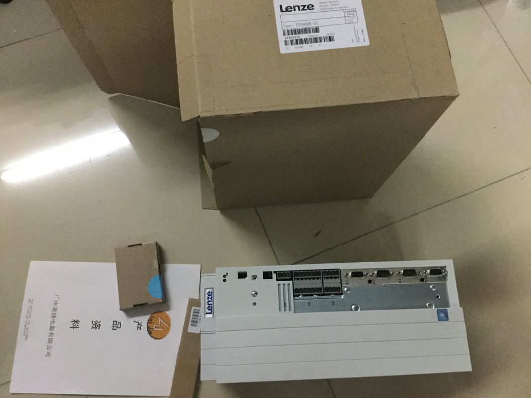
| Brand Name: | LENZE |
| Certification: | CE |
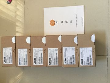
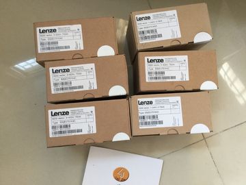
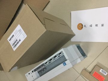
| Model Number: | EVS9327-EI |
| Minimum Order Quantity: | 1pcs |
|---|---|
| Packaging Details: | carton |
| Delivery Time: | in stock |
| Payment Terms: | T/T, Western Union, MoneyGram |
| Supply Ability: | 100pcs/week |
| LENZE: | LENZE | EVS9327-EI: | EVS9327-EI |
|---|---|---|---|
| GERMANY: | GERMANY | Temperature: | 20-90 |
| Material: | Iron | Color: | Black |
| Wire: | Wire |
| If TM_CTRL_DQ = 0, the user program takes over the control and the user can set the output PWM DQA directly via the control bit SET_DQA.A deactivation of the software enable |
|
| (SW_ENABLE = 1 → 0) cancels the current output sequence. The last cycle duration is not completed. STS_ENABLE and the digital output |
|
| PWM DQA are immediately reset to 0. A renewed pulse output is only possible after a restart of the output sequence. |
PWM DQA are immediately reset to 0.
A renewed pulse output is only possible after a restart of the output sequence.
Minimum pulse duration and minimum interpulse period
You assign the minimum pulse duration and the minimum interpulse period with the help of
the parameter "Minimum pulse duration".
● A pulse duration determined by the technology function or PWM channel which is shorter
than the minimum pulse duration will be suppressed.
● A pulse duration determined by the technology function or PWM channel which is longer
than the cycle duration less the minimum interpulse period will be set to the value of the
cycle duration (output switched on permanently).
measured value is changed by the following values
based on the additionally obtained basic error and noise:
• with "voltage", "current" and "resistance" by ±0.1 %
• with "Thermal resistor Pt 100 Standard" by ±0.4 K
• with "Thermal resistor Pt 100 Climatic" by ±0.3 K
• with "Thermal resistor Ni 100 Standard" by ±0.2 K
• with "Thermal resistor Ni 100 Climatic" by ±0.1 K
A detailed description of the basic and operating error is available in the function manual The individual measured values are smoothed by filtering. The smoothing can be set in
4 levels and channel-selective in STEP 7 (TIA Portal).
Smoothing time = Smoothing (k) x configured integration time
The following figure shows the time it takes for the smoothed analog value to reach
approximately 100 % depending on the set smoothing. This is valid for all signal changes at
the analog input.The following table shows the time it takes for the smoothed analog value to reach
approximately 100 % depending on the set smoothing and the set interference frequency
suppression.
Table C- 2 Smoothing time depending on the set smoothing level and interference frequency suppressionThe cycle times (1 ms, 1.04 ms and 1.25 ms) result from the configured interference
frequency suppression. The cycle time is independent of the number of configured analog
channels. The values for the analog input channels are detected sequentially in each cycle.
Reference
For more information on conversion time, cycle time and conversion method, refer to thThe analog values for all measuring ranges that you can use with the analog on-board I/O
are represented in this appendix.
For cross-product information on "analog value processing", refer to the Analog value Each analog value is entered left aligned into the tags. The bits marked with "x" are set to
"0".
Note
This resolution does not apply to temperature values. The digitalized temperature values are
the result of a conversion in the analog on-board I/O.The tables below set out the digitized representation of the input ranges separately for
bipolar and unipolar input ranges. The resolution is 16 bits.The following tables list the decimal and hexadecimal values (codes) of the possible current
measuring ranges.
Table C- 8 Current measuring range ±20 mAThe following tables list the decimal and hexadecimal values (codes) of the possible
resistance-type sensor ranges.
Table C- 10 Resistance-type sensors of 150 Ω, 300 Ω and 600 ΩvWire break" diagnostics enabled
• "Overflow/Underflow" diagnostics
enabled or disabled
("Wire break" diagnostics has a higher
priority than "Overflow/Underflow" diagnostics)
32767 7FFFH "Wire break" or "Cable break" diagnostics
alarm
• "Wire break" diagnostics disabled
• "Overflow/Underflow" diagnostics
enabled
-32767 8000 H • Measured value after leaving the underrange
• Diagnostics alarm "Low limit" violated
• "Wire break" diagnostics disabled
• "Overflow/Underflow" diagnostics
disabled
-32767 8000 H Measured value after leaving the underrangeThe tables below list the decimal and hexadecimal values (codes) of the possible voltage