|
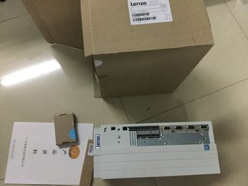
| Place of Origin: | GERMANY |
| Brand Name: | LENZE |
| Certification: | CE |
| Model Number: | EVS9328-ESV100 |
| Minimum Order Quantity: | 1pcs |
|---|---|
| Packaging Details: | carton |
| Delivery Time: | in stock |
| Payment Terms: | T/T, Western Union, MoneyGram |
| Supply Ability: | 100pcs/week |
| LENZE: | LENZE | EVS9328-ESV100: | EVS9328-ESV100 |
|---|---|---|---|
| GERMANY: | GERMANY | Temperature: | 20-90 |
| Color: | Black | Material: | Iron |
| Wire: | Wire |
| your applicationThe supported value range depends on: ? the signal type selected under "Operating mode" |
|
| the value defined under "Increments per revolution" |
|
| ? the value defined under "Reference speed" |
The low limit of the value range
is:
? for the signal type "PTO (A, B
phase-shifted - quadruple)":
0.1 Hz * 60 s/min * 4) / Increments
per revolution
? for the non-quadruple PTO
signal types: (0.1 Hz *
60 s/min) / increments per
revolution
The high limit of the value range
is the minimum of the value:
? 2 * reference speed
and of the value:
? for the signal type "PTO (A, B
phase-shifted - quadruple)":
(100 000 Hz * 60 s/min * 4) /
Increments per revolution
? for the non-quadruple PTO
signal types:
(100 000 Hz * 60 s/min) / Incr
ements per revolutionThe "Increments per
revolution" is used to
define the number of
increments per revolution
(also in microstep
mode), which is required
by the drive for a
revolution.
1 to 1,000,000 200
Fine resolution Bits in incr. actual value
(G1_XIST1)
The parameter defines
the number of bits for
the coding of the fine
resolution in the current
incremental value of
G1_XIST1.
0 0
Stop behavior Quick stop time The parameter "Quick
stop time" defines the
time interval it should
take for the drive to go
from the maximum
speed to a standstill
(OFF3).
1 to 65 535 (ms) 1,000 (ms)
Hardware
inputs /
outputs
Reference switch input The parameter "Reference
switch input"
defines the hardware
input of the reference
switch.
[Input address of the reference
switch DI]
--
Edge selection reference
switch
The parameter "Edge
selection reference
switch" defines the
edge type which is to
be detected by the
reference switch.
Rising edge Rising edge
Falling edge
Measuring input The parameter "Measuring
input" defines the
hardware input of the
measuring input.
[Input address of the measuring
input DI]
--
"Drive ready" input The parameter ""Drive
ready" input" defines
the hardware input of
the input "Drive ready".
[Input addresses of the inputs
"Drive ready" DIn]
--
Pulse output A
for "PTO (pulse (A) and
direction (B))"
The parameter "Pulse
output A" defines the
hardware output for
PTO signal A.
[Output address DQ for PTO
signal A (output frequency
100 kHz)]Read only access
to the parameter
Clock generator backward
(B)
for "PTO (Count up (A)
and Count down (B))"
The "Clock generator
backward (B)" parameter
defines the hardware
output for PTO
signal B.
[Output address 1 of the DQ for
PTO signal B (output frequency
100 kHz)]
grayed out
Read only access
to the parameter
Phase A
for "PTO (A, B phaseshifted)"
and "PTO (A, B
phase-shifted, quadruple)"
The "Clock generator
output (A)" parameter
defines the hardware
output for PTO signal
A.
[Output address of the DQ for
PTO signal A (output frequency
100 kHz)]
grayed out
Read only access
to the parameter
Phase B
for "PTO (A, B phaseshifted)"
and "PTO (A, B
phase-shifted, quadruple)"
The "Clock generator
output (B)" parameter
defines the hardware
output for PTO signal
B.
[Output address 1 of the DQ for
PTO signal B (output frequency
100 kHz)]