|
| Place of Origin: | Japan |
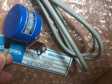
| Brand Name: | Tamagawa |
| Certification: | CE |
| Model Number: | TS5013N69 |
| Minimum Order Quantity: | 1pcs |
|---|---|
| Packaging Details: | carton |
| Delivery Time: | in stock |
| Payment Terms: | T/T, Western Union, MoneyGram |
| Supply Ability: | 100pcs/week |
| TAMAGAWA: | TAMAGAWA | Material: | Iron |
|---|---|---|---|
| Color: | Black | Temperature: | 20-90 |
| Dimension: | 80mm | Japan: | Japan |
| Wire: | Wire | TS5013N69: | TS5013N69 |
TS5013N69
| Incremental encoder acquisition with 2 phase-shifted tracks | Pulse-width modulated output • Configurable substitute values per DQ Diagnostic interrupt X |
| Incremental encoder acquisition with 2 phase-shifted tracks | ardware interrupt --- Isochronous mode X (required for the time stamp and oversampling functions)The technology modules SIWAREX WP521 and SIWAREX WP522 are used for the acquisition and |
| Up to 2 time stamps per cycle (resolution 1 µs) • 32x oversampling |
rocessing of signals from weighing or force transducers. You can connect one scale (WP521) or |
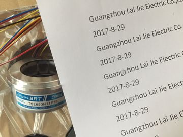
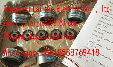
Guang Zhou Lai Jie Electric Co.,LTD
Please contact with “Tommy” for the price
TS3103N156
FACODER
TS3664N2E3
TS5013N60
TS3641N22E7
TS5208N68
TS5210N450
TS4503N1202E200
TS3103N178
TS3664N2E4
TS5013N61
TS3641N2E3
TS5212N351
TS5210N453
TS4503N1205E200
TS3103N255
TS3664N50
TS5016N60
TS3641N12E3
TS5212N510
TS5210N458
TS4503N1828E100
TS3103N302
OAH14BSD
TS3667N1E2
TS5013N63
TS3641N32
TS5213N550
TS5210N530
TS4503N2000E100
TS3103N40
OAS66
TS3667N11E2
TS5016N61
TS3641N38
TS5213N551
TS5210N54
TS4503N2070E100
TS3132N32
rocessing of signals from weighing or force transducers. You can connect one scale (WP521) or two separate scales (WP522) respectively to the modules. The SIWAREX modules offer high
accuracy.
The table below shows the main features of the technology modules for weighing technologyThe power supply of an automation system to be dimensioned according to plant size. The
SIMATIC CPUs are supplied via a load power supply. A system power supply that
supplies the backplane bus is integrated in the CPUs. Depending on the system configuration, you
can expand the integrated system power supply with up to two additional system power supply
modules. If your plant has high power requirements (e.g. I/O load groups), you can connect
additional load power supplies.
The main differences between the two power supplies for the SIMATIC automation system
are listed below:Supplies the system components such as CPU, system power
supply (PS), input/output circuits of the I/O modules and any sensors and
actuators with 24 V DC. You can install the load power supply directly to
the left of the CPU (without connection to the backplane bus).
The supply of the CPU or of the interface module with 24 V DC is optional
if you supply the voltage for the backplane bus via a system power supply.
System power supply (PS) Supplies only internally required system voltage.
Supplies parts of the module electronics and the LEDs.
Configuration example of a system with load power supply and system power
supply
The following figure shows a system configuration with load power supply and additional system
power supplyOverall configuration of power supply
In order to ensure the supply of the modules from the backplane bus, the incoming power is
compared with the required power in the TIA Portal engineering system or in the TIA Selection
Tool.
As early as in the planning stages, make sure that the power fed into the backplane bus is always
greater than or equivalent to the power drawnSystem power supplies supply the internal electronics of the modules with power via the
backplane bus. The table below shows the available system power supply modulesThe load power supply modules with automatic range selection of the input voltage are optimally
adapted in design and functionality to the SIMATIC controller. The table below shows the
available load power supply modulesFor higher output currents and 1-phase or 3-phase infeed
• With redundant installation of the 24 V power supply as protection against failure of a power
pack
• With buffering of the 24 V power supply (e. g. with DC UPS) as protection against power failure
• With selective monitoring of 24 V loads against overload or short-circuitThe individual modules are connected to one another with the U connector. The U connector
establishes the mechanical and electrical connection between the modules. The U connectors are
included in the scope of delivery of the I/O modules.Example: System cabling with SIMATIC TOP connect
For 35 mm modules, the system cabling SIMATIC TOP connect with prefabricated connection
elements is available in two versions:
• Fully modular connection consisting of front connector module, connection cables and
connection modules for connecting sensors and actuators from the field
• Flexible connection, consisting of front connector with single cores for wiring within the cabinet
You can find more information in theThe SIMATIC controllers are integrated into the Totally Integrated Automation Portal. Engineering
with the TIA Portal offers configuration and programming, common data storage and a uniform
operating concept for control, visualization and drives.
The TIA Portal simplifies the integrated engineering in all configuration phases of a plant.You can use the free SIMATIC Automation Tool to run commissioning and maintenance activities
simultaneously on various SIMATIC S7 stations as bulk operation independently of the TIA Portal.
The SIMATIC Automation Tool provides a multitude of functions: