 |
| Place of Origin: | Japan |
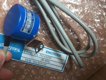
| Brand Name: | Tamagawa |
| Certification: | CE |
| Model Number: | TS5205N450 |
| Minimum Order Quantity: | 1pcs |
|---|---|
| Packaging Details: | carton |
| Delivery Time: | in stock |
| Payment Terms: | T/T, Western Union, MoneyGram |
| Supply Ability: | 100pcs/week |
| TAMAGAWA: | TAMAGAWA | Material: | Iron |
|---|---|---|---|
| Color: | Black | Temperature: | 20-90 |
| Wire: | Wire | Japan: | Japan |
| Dimension: | 70mm | TS5205N450: | TS5205N450 |
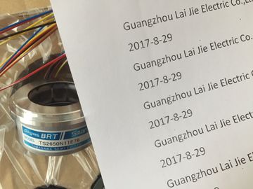
TS5205N450
| If applicable, are all further protective conductor connection points on the automation system |
affected plant units?Are all the modules inserted / installed in accordance with the mounting plan and |
| ET 200MP I/O system connected to the protective conductor? ● Has the connection between reference ground and ground been correctly made on all |
|
| mounting rails? ● Are the required equipotential bonding cables connected with low impedance to the |
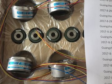
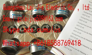
Guang Zhou Lai Jie Electric Co.,LTD
Please contact with “Tommy” for the price
TS4127N1017E235
TS1982N128E6
8001231S
TS3653N4E12
TS5013N64
TS3630N2E3
TS5016N
TS5000N532
TS4231N6E17
TS1982N53E6
800123-2R
TS3653N14E12
TS5420N60
TS3630N2E4
TS5016N60
TS5000N632
TS4231N6E17
TS1982N56E18
TS3653N58E5
TS5778N155
TS3630N3E5
TS5003N632
TS4244N10E24
TS1982N56E18
800123-R-F
TS3653N65E27
TS5208N23
TS3630N101E2
TS5017N56
TS5005N122
TS4244N3E24
TS1983N146E5
TS3653N81E27
corresponding to the configuration with STEP 7 and screwed firmly to the mounting rail?
● Are all the front connectors wired according to the circuit diagram, in the final position,
and inserted on the correct module?
● Are the correct modules installed and connected to each other with U connectors?
● Are U connectors projecting either at the left-hand or right-hand over the outer modules
on the automation system/ET 200MP distributed I/O system?
System power supply or load current supply
● Are all system power supplies and load current supplies switched off?
● Is the power cable connector correctly wired?
● Has the connection to line voltage been made?● The CPU is in the "Factory settings" state or has been reset to factory settings (see
Resetting the CPU to factory settings (Page 293)).
● The SIMATIC memory card is as delivered or has been formatted.
Commissioning procedure
For the first commissioning of an automation system, we recommend the following
procedure:Configure hardware in STEP 7 and perform power balance calculation
(see also "Requirements: CPU as bus device")
Section Power balance calculation
(Page 104)
2 Create user program STEP 7 online help
3 Insert required modules Section Installation (Page 108)
4 Wiring the assembly (system power supplies, front connectors,
etc.)
Section Wiring (Page 122)
5 Insert SIMATIC memory card in the CPU Section Removing/inserting a SIMATIC
memory card on the CPU (Page 226)
6 Switch on the CPU and system power supply See section First power-on of the CPU
(Page 229)
7 Check LEDs The meaning of the LEDs can be found
in the manuals of the modules.
8 Evaluate information on the CPU's display Section CPU display (Page 266)
9 Configure hardware in STEP 7 and download to the CPU Online and diagnostics functions in
STEP 7
10 Test inputs and outputs The following functions are helpful: Monitoring
and modifying tags, testing with
program status, forcing, modifying the
outputs in STOP mode. See section Test
functions and fault resolution (Page 302)Note the following requirements for operation of a CPU as bus device:
● PROFIBUS interface
– The integrated PROFIBUS interface of the CPU is configured using STEP 7 (device
address and bus parameters configured).
– The CPU is connected to the subnet.
– The terminating resistors at the segment boundaries are switched on.
See the PROFIBUS Function Manual PROFINET interface