 |
| Place of Origin: | Japan |
| Brand Name: | Tamagawa |
| Certification: | CE |
| Model Number: | TS5233N430 |
| Minimum Order Quantity: | 1pcs |
|---|---|
| Packaging Details: | carton |
| Delivery Time: | in stock |
| Payment Terms: | T/T, Western Union, MoneyGram |
| Supply Ability: | 100pcs/week |
| TAMAGAWA: | TAMAGAWA | TS5233N430: | TS5233N430 |
|---|---|---|---|
| Material: | Iron | Color: | Black |
| Temperature: | 20-90 | Japan: | Japan |
| Dimension: | 80mm | Wire: | Wire |
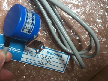
TS5233N430
| for the ET 200MP distributed I/O system in Control data record for the ET 200MP | Slot entries in the control data record outside the station master are ignored by the |
| distributed I/O system (Page 212)In the "Start value" column of the control data records, enter which module is located at | CPU/interface module. |
| hich slot.Observe the following rules: | The control data record must contain the entries up to the last slot of the station option. |
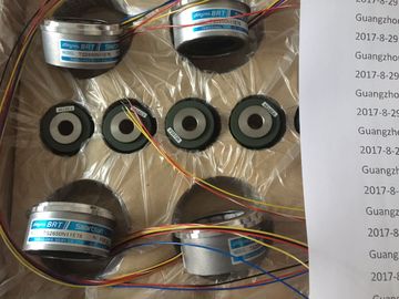
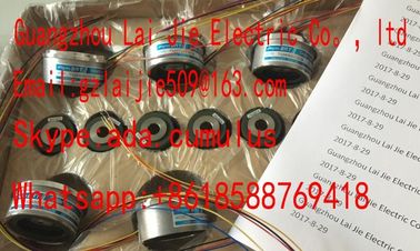
Guang Zhou Lai Jie Electric Co.,LTD
Please contact with “Tommy” for the price
TS5019N60
TS3653N11E2
TS5313N122
TS2228N33E1
TS4507N1002E200
TS3134N52
OSE5K-6-12-108
TS3667N13E8
TS5013N68
TS3653N12E5
TS5320N632
TS2640N141E172
TS4507N1202E200
OSE5KN-6-12-108
TS3674N37
TS5013N69
TS3653N13E8
TS5420
TS2640N181E100
TS4507N1205E200
TS3166N43
TS3679N2E1
TS5208N131
TS3653N1E1
TS5641N150
TS2640N321E64
TS4507N1229E200
TS3212N32
RFH102422
TS3679N3E1
TS5208N111E78
Each slot of a station option may only be present once in the control data record.
● Each slot of a station option may only be assigned to one slot in the station master.
● System power supplies (PS) can also be subject to configuration control.
Note
Configuration control for system power supplies
In the case of a configuration (station option) loaded using a data record, STEP 7 does
not automatically check compliance with the power budget.
Ensure that the power supplied in each power segment of the station option is greater
than or equal to the power drawn.
You can find additional information in the section Power balance calculation (Page 104).
Using communication modules
● Point-to-point communication modules:
Point-to-point communication modules can be used without any restrictions for the
configuration control.
● PROFINET/Ethernet and PROFIBUS communication modules:
CPUs as of firmware version V1.7 support configuration control when using
PROFINET/Ethernet or PROFIBUS communication modules. If PROFINET/Ethernet or
PROFIBUS communication modules, such as a CM 1542-5 (DP master or DP slave) are
inserted in the central configuration, these communication modules cannot be influenced
by the configuration control. You must therefore leave these modules in the slots
preassigned in the station master and enter the slot numbers from the station master in
the control data record ("Station option slot = Station master slot"). In a station option, all
slots up to the communication module furthest from the CPU must be present in the
control data record. Maximum flexibility is achieved by inserting the communication
modules directly to the right of the CPUThe following table shows the slot assignment of the modules for the automation
system:
Table 10- 2 Slot assignment
Slot Modules Comment
0 System power supply (optional) Upstream of CPU
1 CPU Slot 1 is always the CPU
2 - 31 I/O modules/system power supplies, depending on
the station option
Downstream of CPU
Control data record
For configuration control of the automation system, you define a control data record
196 V4.0, which contains a slot assignment. The table below shows the structure of a control
data record with explanations of the individual elements.Block length 4 + number of slots Header
1 Block ID 196
2 Version 4
3 Version 0
4 Slot 0 of the station master Slot assignment in the
station option
Control element
Contains information on which module is
inserted in which slot.
The following rule determines which value
you must enter in the respective byte:
• If the module is included in the station
option, enter the slot number of the
module.
• If the module is not included in the