|
| Place of Origin: | Japan |
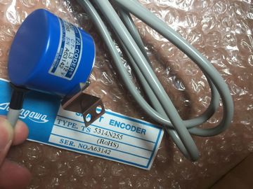
| Brand Name: | Tamagawa |
| Certification: | CE |
| Model Number: | TS5213N550 |
| Minimum Order Quantity: | 1pcs |
|---|---|
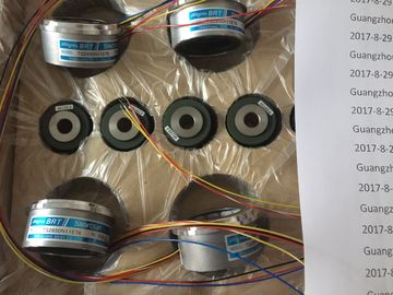
| Packaging Details: | carton |
| Delivery Time: | in stock |
| Payment Terms: | T/T, Western Union, , MoneyGram |
| Supply Ability: | 100pcs/week |
| TAMAGAWA: | TAMAGAWA | Material: | Iron |
|---|---|---|---|
| Color: | Black | Temperature: | 20-90 |
| Dimension: | 80mm | Japan: | Japan |
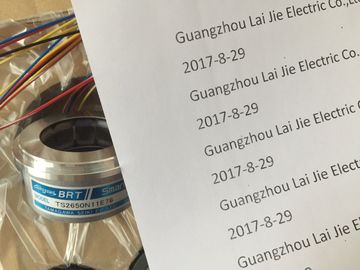
| TS5213N550: | TS5213N550 |
TS5213N550
| Add an external load at the input For sourcing outputs, connect "Load" to "-" | the active state of a sourcing load is opposite that of a |
| shown). For sinking outputs, connect "Load" to "+". Because both sinking | inking load. A source output exhibits positive logic (Q bit and LED are ON when the load has current flow), while a sink |
| and sourcing configurations are supported by the same circuitry, | utput exhibits negative logic (Q bit and LED are OFF when the load has current flow). If the module is plugged in with |
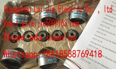
Guang Zhou Lai Jie Electric Co.,LTD
Please contact with “Tommy” for the price
TS5016N63
TS3643N2
TS5308N510
TS20E12
TS4503N2202E200
TS3134N21
TS3667N2E6
TS5016N64
TS3643N212E5
TS530N33E9
TS2151N121E9
TS4503N2036E501
TS3134N22
OIS1000CT3L5V108
TS3667N3E7
TS5017N60
TS3643N233E8
TS5312-N250
TS2151N141E9
TS4506N1202E200
TS3134N317
OSE10243158
TS3667N3E8
TS5019N60
TS3653N11E2
TS5313N122
TS2228N33E1
TS4507N1002E200
TS3134N52
OSE5K-6-12-108
TS3667N13E8
TS5013N68
TS3653N12E5
TS5320N632
TS2640N141E172
TS4507N1202E200
OSE5KN-6-12-108
TS3674N37
no user program, the default for this module is 0 V, which means that a sinking load will be turned ON. Because both sinking and sourcing configurations are supported by the same circuitry, the active state of a sourcing
load is opposite that of a sinking load. A source output exhibits positive logic (Q bit and LED are ON when the load has
current flow), while a sink output exhibits negative logic (Q bit and LED are OFF when the load has current flow). If the
module is plugged in with no user program, the default for this module is 0 V, which means that a sinking load will be
turned ON. When switching frequencies above 20 kHz, it is important that the digital inputs receive a
square wave. Consider the following options to improve the signal quality to the inputs:
Minimize the cable length
Change a driver from a sink only driver to a sinking and sourcing driver
Change to a higher quality cable
Reduce the circuit/components from 24 V to 5 V
Add an external load at the input ① Supports sourcing inputs only
② For sourcing outputs, connect "Load" to "-" (shown). For sinking outputs, connect "Load" to "+". 1 Because both sinking
and sourcing configurations are supported by the same circuitry, the active state of a sourcing load is opposite that of a
sinking load. A source output exhibits positive logic (Q bit and LED are ON when the load has current flow), while a sink
output exhibits negative logic (Q bit and LED are OFF when the load has current flow). If the module is plugged in with
no user program, the default for this module is 0 V, which means that a sinking load will be turned ONDepending on your pulse receiver and cable, an additional load resistor (at least 10% of rated current) may improve
pulse signal quality and noise immunity.
Voltage: 32,511 to 27,649 / -27,649 to -32,512
Current: 32,511 to 27,649 / 0 to -4,864
(Refer to Analog input representation for voltage and Analog input
representation for current.)
Overflow/Underflow (data word) Voltage: 32,767 to 32,512 / -32,513 to -32,768
Current: 32,767 to 32,512 / -4,865 to -32,768
(Refer to Analog input representation for voltage and Analog input
representation for current.)
Maximum withstand voltage / current ±35V / ±40 mA
Smoothing None, weak, medium, or strong (refer to Analog input response
times for step response time.)
Noise rejection 400, 60, 50, or 10 Hz (refer to Analog input response times for
sample rates.)
Accuracy (25°C / -20 to 60°C) ±0.3% / ±0.6% of full scale
Input impedance
Differential
Common mode
Voltage: 220 kΩ; Current: 250 Ω
Voltage: 55 kΩ; Current: 55 kΩ
Behavior on RUN to STOP Last value or substitute value (default value 0)
Measuring principle Actual value conversion
Common mode rejection 400 dB, DC to 60 Hz
Operational signal range Signal plus common mode voltage must be less than +35 V and
greater than -35 V
Isolation (field side to logic) None
Cable length (meters) 100 m, twisted and shielded In an overflow or underflow condition, analog outputs will behave according to the device configuration properties set for
the analog signal module. In the "Reaction to CPU STOP" parameter, select either: Use substitute value or Keep last
valueTable A- 193 Analog output representation for current In an overflow or underflow condition, analog outputs will behave according to the device configuration properties set for
the analog signal module. In the "Reaction to CPU STOP" parameter, select either: Use substitute value or Keep last
value. The overflow and underflow diagnostic alarm information will be reported in the analog data values even if the alarms
are disabled in the module configuration.
2 When wire break alarm is disabled and an open wire condition exists in the sensor wiring, the module may report
random values. The SM 1231 Thermocouple (TC) analog signal module measures the value of voltage
connected to the module inputs.
The SB 1231 Thermocouple analog signal board measures the value of voltage connected
to the signal board inputs. The temperature measurement type can be either
"Thermocouple" or "Voltage".
● "Thermocouple": The value will be reported in degrees multiplied by ten (for example,