|
| Place of Origin: | Japan |
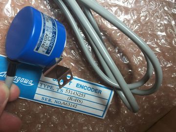
| Brand Name: | Tamagawa |
| Certification: | CE |
| Model Number: | TS2014N311E32 |
| Minimum Order Quantity: | 1pcs |
|---|---|
| Packaging Details: | carton |
| Delivery Time: | in stock |
| Payment Terms: | T/T, Western Union, MoneyGram |
| Supply Ability: | 100pcs/week |
| TAMAGAWA: | TAMAGAWA | TS2014N311E32: | TS2014N311E32 |
|---|---|---|---|
| Japan: | Japan | Material: | Iron |
| Color: | Black | Temperature: | 20-80 |
| Wire: | Wire | Dimension: | 60mm |
| Always 0 (low): (Tag name "AlwaysFALSE") bit is always set to 0. | from 0.5 Hz (slow) to 10 Hz (fast). You can use these bits as control |
| You can assign one byte in M memory for clock memory. Each bit of the byte configured | from 0.5 Hz (slow) to 10 Hz (fast). You can use these bits as control |
| s clock memory generates a square wave pulse. The byte of clock memory provides 8 different frequencies, |
he CPU initializes these bytes on the transition from STOP mode to STARTUP mode. |
TS3103N156
TS2014N311E32
TS1981N56E19
TS1982N126E6
TS1982N128E6
TS1982N53E6
TS1982N56E18
TS1983N146E5
TS252N30E1
TS3503N11E43
TS3062E3
TS3092N11E12
TS3095N2
TS3103N156
TS3103N178
TS3103N255
TS3103N302
TS3103N40
TS3132N32
TS3134N21
TS3134N22
TS3134N317
TS3134N52
bits of the clock memory change synchronously to the CPU clock throughout the STARTUP
and RUN modes.Overwriting the system memory or clock memory bits can corrupt the data in these
functions and cause your user program to operate incorrectly, which can cause damage to
equipment and injury to personnel.
Because both the clock memory and system memory are unreserved in M memory,
instructions or communications can write to these locations and corrupt the data.
Avoid writing data to these locations to ensure the proper operation of these functions, and
always implement an emergency stop circuit for your process or machine.Clock memory configures a byte that cycles the individual bits on and off at fixed intervals.
Each clock bit generates a square wave pulse on the corresponding M memory bit. These
bits can be used as control bits, especially when combined with edge instructions, to trigger
actions in the user code on a cyclic basisThe CPU supports a diagnostics buffer which contains an entry for each diagnostic event.
Each entry includes a date and time the event occurred, an event category, and an event
description. The entries are displayed in chronological order with the most recent event at
the top. Up to 50 most recent events are available in this log. When the log is full, a new
event replaces the oldest event in the log. When power is lost, the events are saved.
The following types of events are recorded in the diagnostics buffer:
● Each system diagnostic event; for example, CPU errors and module errors
● Each state change of the CPU (each power up, each transition to STOP, each transition
to RUN)
To access the diagnostics buffer (Page 680), you must be online. From the "Online &
diagnostics" view, locate the diagnostics buffer under "Diagnostics > Diagnostics buffer". The CPU supports a time-of-day clock. A super-capacitor supplies the energy required to
keep the clock running during times when the CPU is powered down. The super-capacitor
charges while the CPU has power. After the CPU has been powered up at least 24 hours,
then the super-capacitor has sufficient charge to keep the clock running for typically 20 days.
STEP 7 sets the time-of-day clock to system time, which has a default value out of the box or
following a factory rest. To utilize the time-of-day clock, you must set it. Timestamps such as
those for diagnostic buffer entries, data log files, and data log entries are based on the
system time. You set the time of day from the "Set time of day" function (Page 678) in the
"Online & diagnostics" view of the online CPU. STEP 7 then calculates the system time from
the time you set plus or minus the Windows operating system offset from UTC (Coordinated
Universal Time). Setting the time of day to the current local time produces a system time of
UTC if your Windows operating system settings for time zone and daylight savings time
correspond to your locale.
STEP 7 includes instructions (Page 249) to read and write the system time (RD_SYS_T and
WR_SYS_T), to read the local time (RD_LOC_T), and to set the time zone
(SET_TIMEZONE). The RD_LOC_T instruction calculates local time using the time zone and
daylight saving time offsets that you set in the "Time of day" configuration in the general
properties of the CPU (Page 123). These settings enable you to set your time zone for local
time, optionally enable daylight saving time, and specify the start and end dates and times
for daylight saving time. You can also use the SET_TIMEZONE instructions to configure
these settings. You can configure the behavior of the digital and analog outputs when the CPU is in STOP
mode. For any output of a CPU, SB or SM, you can set the outputs to either freeze the value
or use a substitute value:
● Substituting a specified output value (default): You enter a substitute value for each
output (channel) of that CPU, SB, or SM device.
The default substitute value for digital output channels is OFF, and the default substitute
value for analog output channels is 0.