|
| Place of Origin: | Japan |
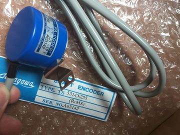
| Brand Name: | Tamagawa |
| Certification: | CE |
| Model Number: | TS2014N312E32 |
| Minimum Order Quantity: | 1pcs |
|---|---|
| Packaging Details: | carton |
| Delivery Time: | in stock |
| Payment Terms: | T/T, Western Union, MoneyGram |
| Supply Ability: | 100pcs/week |
| TAMAGAWA: | TAMAGAWA | TS2014N312E32: | TS2014N312E32 |
|---|---|---|---|
| Material: | Iron | Color: | Black |
| Temperature: | 20-80 | Wire: | Wire |
| Dimension: | 50mm |
| Freezing the outputs to remain in last state: | After power up, the outputs are set to the default substitute value. |
| The outputs retain their current value at the | You configure the behavior of the outputs in Device Configuration. |
| time of the transition from RUN to STOP. | Select the individual |
TS3103N156
TS2014N312E32
TS3103N255
TS3103N302
TS3103N40
TS3132N32
TS3134N21
TS3134N22
TS3134N317
TS3134N52
TS3166
TS3166N43
TS3212N32
TS3214N12
TS3214N13
TS3214N15
TS3214N16
TS3214N44
TS3218
TS3218N42
TS3218N5
TS3250E12
TS3275N125
TS3153N15E18
TS3602N213E8
devices and use the "Properties" tab to configure the outputs for each device.
When the CPU changes from RUN to STOP, the CPU retains the process image and writes
the appropriate values for both the digital and analog outputs, based upon the configurationSTEP 7 facilitates symbolic programming. You create symbolic names or "tags" for the
addresses of the data, whether as PLC tags relating to memory addresses and I/O points or
as local variables used within a code block. To use these tags in your user program, simply
enter the tag name for the instruction parameter.
For a better understanding of how the CPU structures and addresses the memory areas, the
following paragraphs explain the "absolute" addressing that is referenced by the PLC tags.
The CPU provides several options for storing data during the execution of the user program:
● Global memory: The CPU provides a variety of specialized memory areas, including
inputs (I), outputs (Q) and bit memory (M). This memory is accessible by all code blocks
without restriction
● PLC tag table: You can enter symbolic names in the STEP 7 PLC tag table for specific
memory locations. These tags are global to the STEP 7 program and allow programming
with names that are meaningful for your application.
● Data block (DB): You can include DBs in your user program to store data for the code
blocks. The data stored persists when the execution of the associated code block comes
to an end. A "global" DB stores data that can be used by all code blocks, while an
instance DB stores data for a specific FB and is structured by the parameters for the FB.
● Temp memory: Whenever a code block is called, the operating system of the CPU
allocates the temporary, or local, memory (L) to be used during the execution of the
block. When the execution of the code block finishes, the CPU reallocates the local
memory for the execution of other code blocks. Each different memory location has a unique address. Your user program uses these
addresses to access the information in the memory location. References to the input (I) or
output (Q) memory areas, such as I0.3 or Q1.7, access the process image. To immediately
access the physical input or output, append the reference with ":P" (such as I0.3:P, Q1.7:P,
or "Stop:P"). Process image input
I_:P 1
(Physical input)
Immediate read of the physical input points on the CPU,
SB, and SM
Yes No
Copied to physical outputs at the beginning of the scan
cycle
Q No No
Process image output
Q_:P 1
(Physical output)
Immediate write to the physical output points on the
CPU, SB, and SM
Yes No
M
Bit memory
Control and data memory No Yes
(optional)
L
Temp memory
Temporary data for a block local to that block No No
DB
Data block
Data memory and also parameter memory for FBs No Yes
(optional)
1 To immediately access (read or write) the physical inputs and physical outputs, append a ":P" to the address or tag
(such as I0.3:P, Q1.7:P, or "Stop:P").
Each different memory location has a unique address. Your user program uses these
addresses to access the information in the memory location. The absolute address consists
of the following elements:
● Memory area identifier (such as I, Q, or M)