|
| Place of Origin: | Japan |
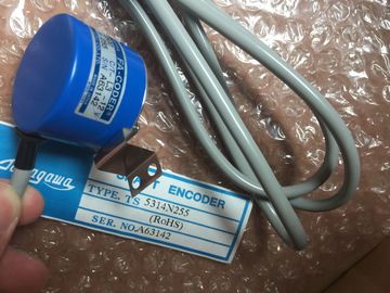
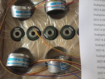
| Brand Name: | Tamagawa |
| Certification: | CE |
| Model Number: | TS2018N303E51 |
| Minimum Order Quantity: | 1pcs |
|---|---|
| Packaging Details: | carton |
| Delivery Time: | in stock |
| Payment Terms: | T/T, Western Union, MoneyGram |
| Supply Ability: | 100pcs/week |
| TAMAGAWA: | TAMAGAWA | Material: | Iron |
|---|---|---|---|
| Color: | Black | Temperature: | 30-80 |
| Wire: | Wire | Dimension: | 50mm |
| TS2018N303E51: | TS2018N303E51 |
TS3103N156
TS2018N303E51
TS3214N44
TS3218
TS3218N42
TS3218N5
TS3250E12
TS3275N125
TS3153N15E18
TS3602N213E8
TS3602N233E8
TS3602N31E8
TS3617N1E1
TS3617N1E2
TS3617N11E1
TS3617N1E3
TS3617N2E4
TS3617N2E5
TS3617N2E6
TS3617N2E7
TS3617N3E10
TS3617N3E8
TS3617N13E8
TS3617N376
TS3617N381
![]()
![]()
![]()
![]()
| Size of the data to be accessed ("B' for Byte, "W" for Word, or "D" for DWord) | |
| the size. You enter only the memory area, the byte location, and the bit location for the data | |
| Starting address of the data (such as byte 3 or word 3) When accessing a bit in the address for a Boolean value, you do not enter a mnemonic for |
(such as I0.0, Q0.1, or M3.4). STEP 7 facilitates symbolic programming. Typically, tags are created either in PLC tags, a
data block, or in the interface at the top of an OB, FC, or FB. These tags include a name,
data type, offset, and comment. Additionally, in a data block, a start value can be specified.
You can use these tags when programming by entering the tag name at the instruction
parameter. Optionally you can enter the absolute operand (memory area, size and offset) at
the instruction parameter. The examples in the following sections show how to enter
absolute operands. The % character is inserted automatically in front of the absolute
operand by the program editor. You can toggle the view in the program editor to one of
these: symbolic, symbolic and absolute, or absolute.
I (process image input): The CPU samples the peripheral (physical) input points just prior to
the cyclic OB execution of each scan cycle and writes these values to the input process
image. You can access the input process image as bits, bytes, words, or double words. Both
read and write access is permitted, but typically, process image inputs are only read.STEP 7 facilitates symbolic programming. Typically, tags are created either in PLC tags, a
data block, or in the interface at the top of an OB, FC, or FB. These tags include a name,
data type, offset, and comment. Additionally, in a data block, a start value can be specified.
You can use these tags when programming by entering the tag name at the instruction
parameter. Optionally you can enter the absolute operand (memory area, size and offset) at
the instruction parameter. The examples in the following sections show how to enter
absolute operands. The % character is inserted automatically in front of the absolute
operand by the program editor. You can toggle the view in the program editor to one of
these: symbolic, symbolic and absolute, or absolute.
I (process image input): The CPU samples the peripheral (physical) input points just prior to
the cyclic OB execution of each scan cycle and writes these values to the input process
image. You can access the input process image as bits, bytes, words, or double words. Both
read and write access is permitted, but typically, process image inputs are only read.I_:P accesses are also restricted to the size of inputs supported by a single CPU, SB, or SM,
rounded up to the nearest byte. For example, if the inputs of a 2 DI / 2 DQ SB are configured
to start at I4.0, then the input points can be accessed as I4.0:P and I4.1:P or as IB4:P.
Accesses to I4.2:P through I4.7:P are not rejected, but make no sense since these points are
not used. Accesses to IW4:P and ID4:P are prohibited since they exceed the byte offset
associated with the SB.
Accesses using I_:P do not affect the corresponding value stored in the input process image. Table 4- 10 Absolute addressing for I memory (immediate)
Bit I[byte address].[bit address]:P I0.1:P
Byte, Word, or Double word I[size][starting byte address]:P IB4:P, IW5:P, or ID12:P
Q (process image output): The CPU copies the values stored in the output process image to
the physical output points. You can access the output process image in bits, bytes, words, or
double words. Both read and write access is permitted for process image outputs.
Table 4- 11 Absolute addressing for Q memory
Bit Q[byte address].[bit address] Q1.1
Byte, Word, or Double word Q[size][starting byte address] QB5, QW10, QD40
By appending a ":P" to the address, you can immediately write to the physical digital and
analog outputs of the CPU, SB or SM. The difference between an access using Q_:P instead
of Q is that the data goes directly to the points being accessed in addition to the output
process image (writes to both places). This Q_:P access is sometimes referred to as an
"immediate write" access because the data is sent immediately to the target point; the target
point does not have to wait for the next update from the output process image.
Because the physical output points directly control field devices that are connected to these
points, reading from these points is prohibited. That is, Q_:P accesses are write-only, as
opposed to Q accesses which can be read or write.
Q_:P accesses are also restricted to the size of outputs supported by a single CPU, SB, or
SM, rounded up to the nearest byte. For example, if the outputs of a 2 DI / 2 DQ SB are
configured to start at Q4.0, then the output points can be accessed as Q4.0:P and Q4.1:P or
as QB4:P. Accesses to Q4.2:P through Q4.7:P are not rejected, but make no sense since
these points are not used. Accesses to QW4:P and QD4:P are prohibited since they exceed
the byte offset associated with the SB.
Accesses using Q_:P affect both the physical output as well as the corresponding value
stored in the output process image.
Table 4- 12 Absolute addressing for Q memory (immediate)
Bit Q[byte address].[bit address]:P Q1.1:P
Byte, Word, or Double word Q[size][starting byte address]:P QB5:P, QW10:P or QD40:P
M (bit memory area): Use the bit memory area (M memory) for both control relays and data
to store the intermediate status of an operation or other control information. You can access
the bit memory area in bits, bytes, words, or double words. Both read and write access is
permitted for M memory. Table 4- 13 Absolute addressing for M memory
Bit M[byte address].[bit address] M26.7
Byte, Word, or Double Word M[size][starting byte address] MB20, MW30, MD50
Temp (temporary memory): The CPU allocates the temp memory on an as-needed basis.
The CPU allocates the temp memory for the code block at the time when the code block is