 |
| Place of Origin: | Japan |
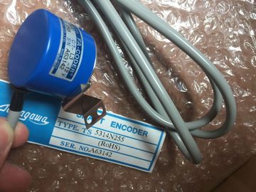
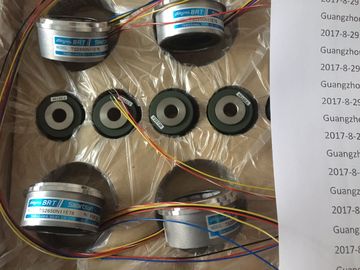
| Brand Name: | Tamagawa |
| Certification: | CE |
| Model Number: | TS2142N1E63 |
| Minimum Order Quantity: | 1pcs |
|---|---|
| Packaging Details: | carton |
| Delivery Time: | in stock |
| Payment Terms: | T/T, Western Union, MoneyGram |
| Supply Ability: | 100pcs/week |
| TAMAGAWA: | TAMAGAWA | Material: | Iron |
|---|---|---|---|
| Color: | Black | Temperature: | 30-80 |
| Japan: | Japan | TS2142N1E63: | TS2142N1E63 |
| Wire: | Wire | Dimension: | 60mm |
| DB (data block): Use the DB memory for storing various types of data, including intermediate | |
| status of an operation or other control information parameters for FBs, and data structures | |
| required for many instructions such as timers and counters. You can access data block |
TS3103N156
TS2142N1E63
TS3630N1E2
TS3630N2E3
TS3630N2E4
TS3630N3E5
TS3630N101E2
TS3630N102E4
TS3630N22E3
TS3630N22E4
TS3631N1E1
TS3636N6
TS3641N1E1
TS3641N21E6
TS3641N22E7
TS3641N2E3
TS3641N12E3
TS3641N32
TS3641N38
TS3643N2
TS3643N212E5
TS3643N233E8
TS3653N11E2
TS3653N12E5
TS3653N13E8
memory in bits, bytes, words, or double words. Both read and write access is permitted for
read/write data blocks. Only read access is permitted for read-only data blocks.
Table 4- 14 Absolute addressing for DB memory
Bit DB[data block number].DBX[byte
address].[bit address]
DB1.DBX2.3
Byte, Word, or Double
Word
DB[data block number].DB [size][starting
byte address]
DB1.DBB4, DB10.DBW2,
DB20.DBD8
Note
When you specify an absolute address, STEP 7 precedes this address with a "%" character
to indicate that it is an absolute address. While programming, you can enter an absolute
address either with or without the "%" character (for example %I0.0 or I.0). If omitted,
STEP 7 supplies the "%" characteWhen you add a CPU and I/O modules to your
configuration screen, I and Q addresses are
automatically assigned. You can change the
default addressing by selecting the address field in
the configuration screen and typing new numbers.
Digital inputs and outputs are assigned in
groups of 8 points (1 byte), whether the module
uses all the points or not.
Analog inputs and outputs are assigned in
groups of 2 points (4 bytes).
The figure shows an example of a CPU 1214C with two SMs and one SB. In this example,
you could change the address of the DI8 module to 2 instead of 8. The tool will assist you by
changing address ranges that are the wrong size or conflict with other addresses. Analog signal modules provide input signals or expect output values that represent either a
voltage range or a current range. These ranges are ±10V, ±5V, ±2.5V, or 0 - 20mA. The
values returned by the modules are integer values where 0 to 27648 represents the rated
range for current, and -27648 to 27648 for voltage. Anything outside the range represents
either an overflow or underflow. See the tables for analog input representation (Page 770)
and analog output representation (Page 771) for details.
In your control program, you probably need to use these values in engineering units, for
example to represent a volume, temperature, weight or other quantitative value. To do this
for an analog input, you must first normalize the analog value to a real (floating point) value
from 0.0 to 1.0. Then you must scale it to the minimum and maximum values of the
engineering units that it represents. For values that are in engineering units that you need to
convert to an analog output value, you first normalize the value in engineering units to a
value between 0.0 and 1.0, and then scale it between 0 and 27648 or -27648 to 27648,
depending on the range of the analog module. STEP 7 provides the NORM_X and SCALE_X
instructions (Page 219) for this purpose. You can also use the CALCULATE instruction
(Page 198) to scale the analog values (Page 33)Data types are used to specify both the size of a data element as well as how the data are to
be interpreted. Each instruction parameter supports at least one data type, and some
parameters support multiple data types. Hold the cursor over the parameter field of an
instruction to see which data types are supported for a given parameter.
A formal parameter is the identifier on an instruction that marks the location of data to be
used by that instruction (example: the IN1 input of an ADD instruction). An actual parameter
is the memory location (preceded by a "%" character) or constant containing the data to be
used by the instruction (example %MD400 "Number_of_Widgets"). The data type of the
actual parameter specified by you must match one of the supported data types of the formal
parameter specified by the instruction.
When specifying an actual parameter, you must specify either a tag (symbol) or an absolute
(direct) memory address. Tags associate a symbolic name (tag name) with a data type,
memory area, memory offset, and comment, and can be created either in the PLC tags
editor or in the Interface editor for a block (OB, FC, FB and DB). If you enter an absolute
address that has no associated tag, you must use an appropriate size that matches a
supported data type, and a default tag will be created upon entry.
All data types except String are available in the PLC tags editor and the block Interface
editors. String is available only in the block Interface editors. You can also e