|
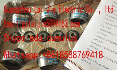
| Place of Origin: | Japan |
| Brand Name: | Tamagawa |
| Certification: | CE |
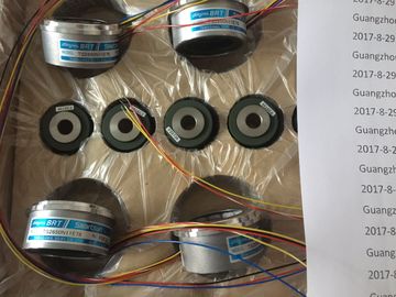
| Model Number: | TS2640N321E64 |
| Minimum Order Quantity: | 1pcs |
|---|---|
| Packaging Details: | carton |
| Delivery Time: | in stock |
| Payment Terms: | T/T, Western Union, MoneyGram |
| Supply Ability: | 100pcs/week |
| TAMAGAWA: | TAMAGAWA | TS2640N321E64: | TS2640N321E64 |
|---|---|---|---|
| Material: | Iron | Color: | Black |
| Japan: | Japan | Wire: | Wire |
| Dimension: | 49mm | Temperature: | 20-80 |
| down slightly to engage the hook. | Slide the tab fully to the left. |
| 4. Lock the connector into place: | To engage the connector, you must slide the connector |
| Place a screwdriver beside the tab on the top of the signal module. |
To engage the connector, you must slide the connector |
TS3103N156
TS2640N321E64
TS3679N3E1
TS3682N1
TS3682N2
TS3684N11E3
TS3684N12E6
TS3684N13E8
TS3684N1E3
TS3684N2E6
TS3684N3E8
TS3692N103
TS3692N41
TS3692N42
TS3699N112
TS3699N172
TS3699N232
TS3738N1E7
TS3738N1E7
TS3741N3E8
TS374
TS3762N15E4
TS4126N1017E235
TS4127N1017E215
locked into place. 1. Ensure that the CPU and all equipment are
disconnected from electrical power.
2. Unlock the connector:
– Place a screwdriver beside the tab on the top of
the signal module.
– Press down slightly and slide the tab fully to the
right.
3. Lift the connector up slightly to disengage the hook
extension.
4. Remove the female connector. Before installing the TS (Teleservice) Adapter IE Basic, you must first connect the
TS Adapter and a TS module.
Available TS modules:
● TS module RS232
● TS module Modem
● TS module GSM
● TS module ISDN The TS module can be damaged if you touch the contacts of the plug connector ④of the
TS module. Follow ESD guidelines in order to avoid damaging the TS module through
electrostatic discharge. Before connecting a TS module and TS Adapter, make sure that
both are in an idle state. Before connecting a TS module and TS adapter basic unit, ensure that the contact pins ④
are not bent. When connecting, ensure that the male connector and guide elements are
positioned correctly.
Only connect a TS module into the TS adapter. Do not force a connection of the TS adapter
to a different device, such as an CPU. Do not change the mechanical construction
of the connector, and do not remove or damage the guide elements. The SIM card may only be removed or inserted if the TS module GSM is de-energized. Use a sharp object to press
the eject button of the SIM
card tray (in the direction of
the arrow) and remove the
SIM card tray. Place the SIM card in the SIM
card tray as shown and put
the SIM card tray back into its
slotEnsure that the SIM card tray is correctly oriented in the card tray. Otherwise, the SIM card
will not make connection with the module, and the eject button may not remove the card tray.
3.3.8.3 Installing the TS adapter unit
Prerequisites: You must have connected the TS Adapter and a TS module together, and the
DIN rail must have been installed.
Note
If you install the TS unit vertically or in high-vibration environment, the TS module can
become disconnected from the TS Adapter. Use an end bracket 8WA1 808 on the DIN rail to
ensure that the modules remain connectenstallation:
1. Hook the TS Adapter with attached TS module ① on the DIN rail ②.
2. Rotate the unit back until it engages.
3. Push in the DIN rail clip on each module to attach the each module to
the rail.
ཱ
Removal:
1. Remove the analog cable and Ethernet cable from the underside of
the TS Adapter.
2. Remove power from the TS Adapter.
3. Use a screwdriver to disengage the rail clips on both modules.
4. Rotate the unit upwards to remove the unit from the DIN rail. Prerequisites: You must have connected the TS Adapter and TS module.
1. Move the attachment slider ① to the backside of the TS Adapter and TS module in the
direction of the arrow until it engages.
2. Screw the TS Adapter and TS module to the position marked with ② to the designated
assembly wall. iring guidelines
Proper grounding and wiring of all electrical equipment is important to help ensure the
optimum operation of your system and to provide additional electrical noise protection for
your application and the . Refer to the technical specifications (Page 699) for the
wiring diagrams.
Prerequisites