 |
| Place of Origin: | Japan |
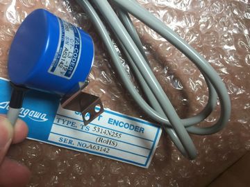
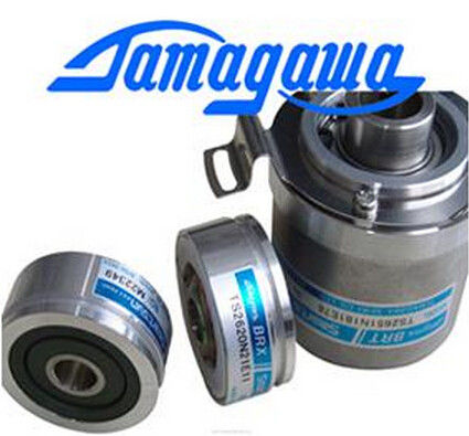
| Brand Name: | Tamagawa |
| Certification: | CE |
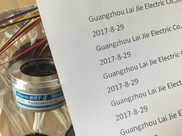
| Model Number: | TS2641N31E64 |
| Minimum Order Quantity: | 1pcs |
|---|---|
| Packaging Details: | carton |
| Delivery Time: | in stock |
| Payment Terms: | T/T, Western Union, MoneyGram |
| Supply Ability: | 100pcs/week |
| TAMAGAWA: | TAMAGAWA | TS2641N31E64: | TS2641N31E64 |
|---|---|---|---|
| Japan: | Japan | Material: | Iron |
| Color: | Black | Dimension: | 70mm |
| Wire: | Wire |
| Before you ground or install wiring to any electrical device, ensure that the power to that | |
| equipment has been turned off. Also, ensure that the power to any related equipment has | |
| been turned off. Ensure that you follow all applicable electrical codes when wiring the and related |
TS3103N156
TS2641N31E64
TS3699N232
TS3738N1E7
TS3738N1E7
TS3741N3E8
TS374
TS3762N15E4
TS4126N1017E235
TS4127N1017E215
TS4127N1017E235
TS4231N6E17
TS4231N6E17
TS4244N10E24
TS4244N3E24
TS4502N1000E200
TS4502N1202E200
TS4502N2000E100
TS4503N1000E200
TS4503N1007E200
TS4503N1022E100
TS4503N1022E200
TS4503N1202E200
TS4503N1205E200
equipment. Install and operate all equipment according to all applicable national and local
standards. Contact your local authorities to determine which codes and standards apply to
your specific case.
WARNING
Installation or wiring the or related equipment with power applied could cause
electric shock or unexpected operation of equipment. Failure to disable all power to the S7-
1200 and related equipment during installation or removal procedures could result in death,
severe personal injury, and/or damage due to electric shock or unexpected equipment
operation.
Always follow appropriate safety precautions and ensure that power to the is
disabled before attempting to install or remove the or related equipment.
Always take safety into consideration as you design the grounding and wiring of your S7-
1200 system. Electronic control devices, such as the , can fail and can cause
unexpected operation of the equipment that is being controlled or monitored. For this reason,
you should implement safeguards that are independent of the to protect against
possible personal injury or equipment damage.
WARNING
Control devices can fail in an unsafe condition, resulting in unexpected operation of
controlled equipment. Such unexpected operations could result in death, severe personal
injury and/or property damage.
Use an emergency stop function, electromechanical overrides, or other redundant
safeguards that are independent of the . AC power supply boundaries and I/O boundaries to AC circuits have been designed
and approved to provide safe separation between AC line voltages and low voltage circuits.
These boundaries include double or reinforced insulation, or basic plus supplementary
insulation, according to various standards. Components which cross these boundaries such
as optical couplers, capacitors, transformers, and relays have been approved as providing
safe separation. Isolation boundaries which meet these requirements have been identified in
product data sheets as having 1500 VAC or greater isolation. This designation is
based on a routine factory test of (2Ue + 1000 VAC) or equivalent according to approved
methods. safe separation boundaries have been type tested to 4242 VDC.
The sensor supply output, communications circuits, and internal logic circuits of an
with included AC power supply are sourced as SELV (safety extra-low voltage) according to
EN 61131-2. To maintain the safe character of the low voltage circuits, external connections to
communications ports, analog circuits, and all 24 V nominal power supply and I/O circuits
must be powered from approved sources that meet the requirements of SELV, PELV, Class
2, Limited Voltage, or Limited Power according to various standards.
WARNING
Use of non-isolated or single insulation supplies to supply low voltage circuits from an AC
line can result in hazardous voltages appearing on circuits that are expected to be touch
safe, such as communications circuits and low voltage sensor wiring.
Such unexpected high voltages could cause electric shock resulting in death, severe
personal injury and/or property damage.
Only use high voltage to low voltage power converters that are approved as sources of
touch safe, limited voltage circuits. To maintain the safe character of the low voltage circuits, external connections to
communications ports, analog circuits, and all 24 V nominal power supply and I/O circuits
must be power