 |
| Place of Origin: | Japan |
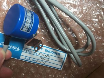
| Brand Name: | Tamagawa |
| Certification: | CE |
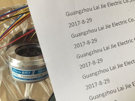
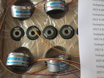
| Model Number: | TS2650N1E78 |
| Minimum Order Quantity: | 1pcs |
|---|---|
| Packaging Details: | carton |
| Delivery Time: | in stock |
| Payment Terms: | T/T, Western Union, MoneyGram |
| Supply Ability: | 100pcs/week |
| TAMAGAWA: | TAMAGAWA | Japan: | Japan |
|---|---|---|---|
| Color: | Black | Wire: | Wire |
| Material: | Iron | TS2650N1E78: | TS2650N1E78 |
| Temperature: | 20-80 |
| , Limited Voltage, or Limited Power according to various standards. WARNING |
safe, such as communications circuits and low voltage sensor wiring. Such unexpected high voltages could cause electric shock resulting in death, severe personal injury and/or property damage. |
| se of non-isolated or single insulation supplies to supply low voltage circuits from an AC | uch unexpected high voltages could cause electric shock resulting in death, severe personal injury and/or property damage. |
| line can result in hazardous voltages appearing on circuits that are expected to be touch | uch unexpected high voltages could cause electric shock resulting in death, severe personal injury and/or property damage. |
TS3103N156
TS2650N1E78
TS4502N1202E200
TS4502N2000E100
TS4503N1000E200
TS4503N1007E200
TS4503N1022E100
TS4503N1022E200
TS4503N1202E200
TS4503N1205E200
TS4503N1828E100
TS4503N2000E100
TS4503N2070E100
TS4503N2202E200
TS4503N2036E501
TS4506N1202E200
TS4507N1002E200
TS4507N1202E200
TS4507N1205E200
TS4507N1229E200
TS4507N2000E100
TS4507N2070E100
TS4507N2405E200
Only use high voltage to low voltage power converters that are approved as sources of
touch safe, limited voltage circuits. All modules have removable connectors for user wiring. To prevent loose
connections, ensure that the connector is seated securely and that the wire is installed
securely into the connector. To avoid damaging the connector, be careful that you do not
over-tighten the screws. The maximum torque for the CPU and SM connector screw is 0.56
N-m (5 inch-pounds). The maximum torque for the SB connector screw is 0.33 N-m (3 inchpounds).
To help prevent unwanted current flows in your installation, the provides isolation
boundaries at certain points. When you plan the wiring for your system, you should consider
these isolation boundaries. Refer to the technical specifications for the amount of isolation
provided and the location of the isolation boundaries. Do not depend on isolation boundaries
rated less than 1500 VAC as safety boundaries.
Guidelines for lamp loads
Lamp loads are damaging to relay contacts because of the high turn-on surge current. This
surge current will nominally be 10 to 15 times the steady state current for a Tungsten lamp.
A replaceable interposing relay or surge limiter is recommended for lamp loads that will be
switched a large number of times during the lifetime of the application.
Guidelines for inductive loadsYou should equip inductive loads with suppression circuits to limit voltage rise when thecontrol output turns off. Suppression circuits protect your outputs from premature failure dueto the high voltages associated with turning off inductive loads. In addition, suppressioncircuits limit the electrical noise generated when switching inductive loads. Placing anexternal suppression circuit so that it is electrically across the load, and physically located
near the load is most effective in reducing electrical noise.DC outputs include internal suppression circuits that are adequate for the inductive
loads in most applications. Since relay output contacts can be used to switch eithera DC or an AC load, internal protection is not provided.
NoteThe effectiveness of a given suppression circuit depends on the application, and you mustverify it for your particular use. Always ensure that all components used in your suppressioncircuit are rated for use in the application. In most applications, the addition of a diode (A)
across a DC inductive load is suitable, but if yourapplication requires faster turn-off times, then the
addition of a Zener diode (B) is recommended. Besure to size your Zener diode properly for the amountof current in your output circuit. When you use a relay output to switch 115 V/230
VAC loads, place the appropriately rated resistorcapacitor-metaloxide varistor (MOV) circuit across
the AC load. Ensure that the working voltage of the
MOV is at least 20% greater than the nominal linevoltage. The CPU supports the following types of code blocks that allow you to create an efficient
structure for your user program: