|
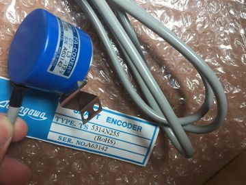
| Place of Origin: | Japan |
| Brand Name: | Tamagawa |
| Certification: | CE |
| Model Number: | TS5208N510 |
| Minimum Order Quantity: | 1pcs |
|---|---|
| Packaging Details: | carton |
| Delivery Time: | in stock |
| Payment Terms: | T/T, Western Union, MoneyGram |
| Supply Ability: | 100pcs/week |
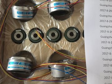
| TAMAGAWA: | TAMAGAWA | Material: | Iron |
|---|---|---|---|
| TS5208N510: | TS5208N510 | Wire: | Wire |
| Japan: | Japan | Color: | Black |
| Temperature: | 20-80 | Dimension: | 60mm |
| process image output area instead of writing to the actual physical outputs. | |
| This process provides consistent logic through the execution of the user instructions for a given cycle and prevents the flickering of physical output points that might change state |
|
| multiple times in the process image output areaYou can specify whether digital and analog I/O points are to be automatically updated and stored in the process image. If you insert a module in the device view, its data is located in |
TS3103N156
TS5208N510
TS3630N11E1
TS3630N11E2
TS3630N12E3
TS3630N12E4
TS3630N13E5
TS3630N13E6
FA-CODER
TS5214N566
TS5205N450
TS5205N454
TS5205
N450
TS5205
N454
TS5205N452
TS5205
N452
TS5207
TS5208
TS5212
TS5213
TS5214
You can insert or remove a SIMATIC memory card while the CPU is under power.
However, inserting or removing a memory card when the CPU is in RUN mode causes
the CPU to go to STOP mode. Insertion or removal of a memory card when the CPU is in RUN mode causes the CPU
to go to STOP, which might result in in damage to the equipment or the process being
controlled.
Whenever you insert or remove a memory card, the CPU immediately goes to STOP
mode. Before inserting or removing a memory card, always ensure that the CPU is not
actively controlling a machine or process. Always install an emergency stop circuit for
your application or process.
● If you insert or remove a module in a distributed I/O rack (PROFINET or PROFIBUS)
when the CPU is in RUN mode, the CPU generates an entry in the diagnostics buffer and
stays in RUN mode.
Under the default configuration, all local digital and analog I/O points are updated
synchronously with the scan cycle using an internal memory area called the process image.
The process image contains a snapshot of the physical inputs and outputs (the physical I/O
points on the CPU, signal board, and signal modules).
The CPU performs the following tasks:
● The CPU writes the outputs from the process image output area to the physical outputs.
● The CPU reads the physical inputs just prior to the execution of the user program and
stores the input values in the process image input area. This ensures that these values
remain consistent throughout the execution of the user instructions.
● The CPU executes the logic of the user instructions and updates the output values in the
the process image of the CPU (default). The CPU handles the data exchange between the
module and the process image area automatically during the update of the process image.
To remove digital or analog points from the process-image automatic update, select the
appropriate device in Device configuration, view the Properties tab, expand if necessary to
locate the desired I/O points, and then select "IO addresses/HW identifier". Then change the
entry for "Process image:" from "Cyclic PI" to "---". To add the points back to the processimage
automatic update, change this selection back to "Cyclic PI".
You can immediately read physical input values and immediately write physical output
values when an instruction executes. An immediate read accesses the current state of the
physical input and does not update the process image input area, regardless of whether the
point is configured to be stored in the process image. An immediate write to the physical
output updates both the process image output area (if the point is configured to be stored in
the process image) and the physical output point. Append the suffix ":P" to the I/O address if
you want the program to immediately access I/O data directly from the physical point instead
of using the process image.
The CPU supports distributed I/O for both PROFINET and PROFIBUS networks (Page 423).
4.1.1 Operating modes of the CPU
The CPU has three modes of operation: STOP mode, STARTUP mode, and RUN mode.
Status LEDs on the front of the CPU indicate the current mode of operation.
● In STOP mode, the CPU is not executing the program. You can download a project.
● In STARTUP mode, the startup OBs (if present) are executed once. Interrupt events are
not processed during the startup mode.
● In RUN mode, the program cycle OBs are executed repeatedly. Interrupt events can
occur and be processed at any point within the RUN mode. Some parts of a project can
be downloaded in RUN mode (Page 690).
The CPU supports a warm restart for entering the RUN mode. Warm restart does not include
a memory reset. All non-retentive system and user data are initialized at warm restart.
Retentive user data is retained. A memory reset clears all work memory, clears retentive and non-retentive memory areas,
and copies load memory to work memory. A memory reset does not clear the diagnostics
buffer or the permanently saved values of the IP address.
Note
When you download one or more DBs from STEP 7 V11 to an V2 CPU, the
retentive and non-retentive values of those DBs are set to their start values. The next
transition to RUN performs a warm restart, setting all non-retentive data to their start values
and setting all retentive data to their retained values.
When you download project elements (such as device configuration, code blocks or DBs)
from STEP 7 V10.5 to any CPU or from STEP 7 V11 to an V1 CPU (or a
V2 CPU that has been configured as a V1 CPU), the next transition to RUN mode resets all
of the DBs in the project to their start values.
You can configure the "startup after POWER ON" setting of the CPU. This configuration item
appears under the "Device configuration" for the CPU under "Startup". When power is
applied, the CPU performs a sequence of power-up diagnostic checks and system
initialization. During system initialization the CPU deletes all non-retentive bit memory and
resets all non-retentive DB contents to the initial values from load memory. The CPU retains
retentive bit memory and retentive DB contents and then enters the appropriate operating
mode. Certain detected errors prevent the CPU from entering the RUN mode. The CPU
supports the following configuration choices: