|
| Place of Origin: | Japan |
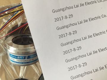
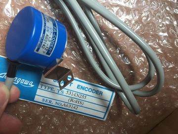
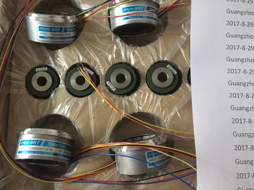
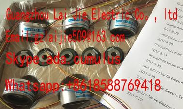
| Brand Name: | Tamagawa |
| Certification: | CE |
| Model Number: | TS5208N530 |
| Minimum Order Quantity: | 1pcs |
|---|---|
| Packaging Details: | carton |
| Delivery Time: | in stock |
| Payment Terms: | T/T, Western Union, MoneyGram |
| Supply Ability: | 100pcs/week |
| TAMAGAWA: | TAMAGAWA | TS5208N530: | TS5208N530 |
|---|---|---|---|
| Japan: | Japan | Color: | Black |
| Material: | Iron | Wire: | Wire |
| Temperature: | 20-80 |
TS3103N156
TS5208N530
TS5205N452
TS5205
N452
TS5207
TS5208
TS5212
TS5213
TS5214
TS5231
TS5217
TS5233
TS5150
TS5300
TS5100
TS5000
TS5080
TS5170
TS5410
TS5200N500
TS5146
TS5270
TS5610
No restart (stay in STOP mode)
● Warm restart - RUN
● Warm restart - mode prior to POWER OFF The CPU can enter STOP mode due to repairable faults, such as failure of a
replaceable signal module, or temporary faults, such as power line disturbance or erratic
power up event.
If the CPU has been configured to "Warm restart mode prior to POWER OFF", it will not
return to RUN mode when the fault is repaired or removed until it receives a new
command from STEP 7 to go to RUN. Without a new command, the STOP mode is
retained as the mode prior to POWER OFF.
CPUs that are intended to operate independently of a STEP 7 connection should
typically be configured to "Warm restart - RUN" so that the CPU can be returned to RUN
mode by a power cycle following the removal of fault conditions. You can change the current operating mode using the "STOP" or "RUN" commands from the
online tools of the programming software. You can also include a STP instruction in your
program to change the CPU to STOP mode. This allows you to stop the execution of your
program based on the program logic.
● In STOP mode, the CPU handles any communication requests (as appropriate) and
performs self-diagnostics. The CPU does not execute the user program, and the
automatic updates of the process image do not occur.
You can download your project only when the CPU is in STOP mode.
● In STARTUP and RUN modes, the CPU performs the tasks shown in the following figure. Clears the I (image) memory area ① Writes Q memory to the physical outputs
B Initializes the outputs with either the
last value or the substitute value
② Copies the state of the physical inputs to I
memory
C Executes the startup OBs ③ Executes the program cycle OBs
D Copies the state of the physical inputs
to I memory
④ Performs self-test diagnostics
E Stores any interrupt events into the
queue to be processed after entering
RUN mode
⑤ Processes interrupts and communications
during any part of the scan cycle
F Enables the writing of Q memory to the
physical outputs
Whenever the operating mode changes from STOP to RUN, the CPU clears the process
image inputs, initializes the process image outputs and processes the startup OBs. Any read
accesses to the process-image inputs by instructions in the startup OBs read zero rather
than the current physical input value. Therefore, to read the current state of a physical input
during the startup mode, you must perform an immediate read. The startup OBs and any
associated FCs and FBs are executed next. If more than one startup OB exists, each is
executed in order according to the OB number, with the lowest OB number executing first. Each startup OB includes startup information that helps you determine the validity of
retentive data and the time-of-day clock. You can program instructions inside the startup
OBs to examine these startup values and to take appropriate action. The following startup
locations are supported by the Startup OBs:
Table 4- 1 Startup locations supported by the startup OB The CPU also performs the following tasks during the startup processing.
● Interrupts are queued but not processed during the startup phase
● No cycle time monitoring is performed during the startup phase
● Configuration changes to HSC (high-speed counter), PWM (pulse-width modulation), and
PtP (point-to-point communication) modules can be made in startup