 |
| Place of Origin: | Japan |
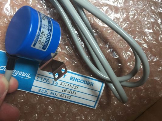
| Brand Name: | Tamagawa |
| Certification: | CE |
| Model Number: | TS5210N450 |
| Minimum Order Quantity: | 1pcs |
|---|---|
| Packaging Details: | carton |
| Delivery Time: | in stock |
| Payment Terms: | T/T, Western Union, MoneyGram |
| Supply Ability: | 100pcs/week |
| TAMAGAWA: | TAMAGAWA | TS5210N450: | TS5210N450 |
|---|---|---|---|
| Japan: | Japan | Color: | Black |
| Material: | Iron | Temperature: | 30-80 |
| WIRE: | Wire | Dimension: | 80mm |
| execute the cyclic interrupt OB (the cyclic event is at a higher priority class than the program | the same scan time can be offset from one another by the phase shift amount. The default |
| cycle event). Only one cyclic interrupt OB can be attached to a cyclic event. |
phase shift is 0. To change the initial phase shift, or to change the initial scan time for a |
| ach cyclic event can be assigned a phase shift so that the execution of cyclic interrupts with |
TS5210N450
TS5214N510
TS2014N182E32
TS3653N2E5
TS5320N510
TS5016N-60
TS5016N60
TS5305N616
TS5008N12238
TS5214N564
TS5212N569
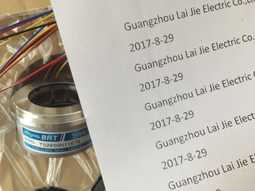
TS2651N111E78
TS2014N181E32
TS-5208N130
TS5207N76
TS5246N160
TS5312N616-2000C-T
TS5312N616
TS5217N530
DIH35-5000C/T-P8-L6-5V
OIH100-1024C/T-P2-12V
TS5233N430
DIH48-6000C/T-P8-L6-5V
TS5246N430
cyclic event, right click on the cyclic interrupt OB in the project tree, click "Properties", then
click "Cyclic interrupt", and enter the new initial values. You can also query and change the
scan time and the phase shift from your program using the Query cyclic interrupt
(QRY_CINT) and Set cyclic interrupt (SET_CINT) instructions. Scan time and phase shift
values set by the SET_CINT instruction do not persist through a power cycle or a transition
to STOP mode; scan time and phase shift values will return to the initial values following a
power cycle or a transition to STOP. The CPU supports a total of four cyclic and time-delay
interrupt events.
The startup event happens one time on a STOP to RUN transition and causes the startup
OBs to be executed. Multiple OBs can be selected for the startup event. The startup OBs are
executed in numerical order.
The time delay interrupt events allow you to configure the execution of an interrupt OB after
a specified delay time has expired. The delay time is specified with the SRT_DINT
instruction. The time delay events will interrupt the program cycle to execute the time delay
interrupt OB. Only one time delay interrupt OB can be attached to a time delay event. The
CPU supports four time delay events.
The hardware interrupt events are triggered by a change in the hardware, such as a rising or
falling edge on an input point, or a HSC (High Speed Counter) event. There can be one
interrupt OB selected for each hardware interrupt event. The hardware events are enabled in
Device configuration. The OBs are specified for the event in the Device configuration or with
an ATTACH instruction in the user program. The CPU supports several hardware interrupt
events. The exact events are based on the CPU model and the number of input points. The time and diagnostic error interrupt events are triggered when the CPU detects an error.
These events are at a higher priority class that the other interrupt events and can interrupt
the execution of the time delay, cyclic and hardware interrupt events. One interrupt OB can
be specified for each of the time error and diagnostic error interrupt events.
Understanding event execution priorities and queuing
The number of pending (queued) events from a single source is limited, using a different