 |
| Place of Origin: | Japan |
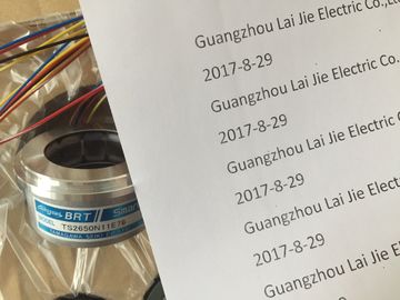
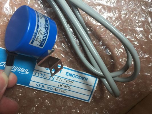
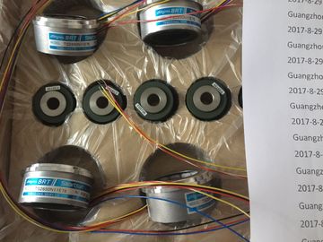
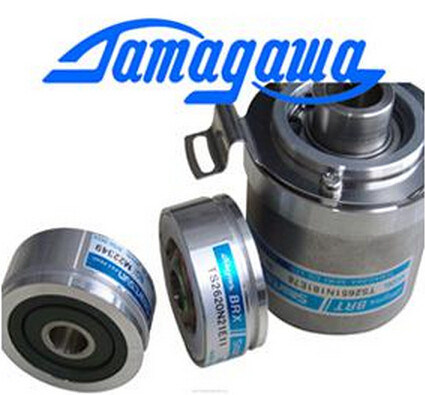
| Brand Name: | Tamagawa |
| Certification: | CE |
| Model Number: | TS5210N458 |
| Minimum Order Quantity: | 1pcs |
|---|---|
| Packaging Details: | carton |
| Delivery Time: | in stock |
| Payment Terms: | T/T, Western Union, MoneyGram |
| Supply Ability: | 100pcs/week |
| TAMAGAWA: | TAMAGAWA | Japan: | Japan |
|---|---|---|---|
| TS5210N458: | TS5210N458 | Material: | Iron |
| Color: | Black | Temperature: | 20-80 |
| Wire: | Wire | Dimension: | 70mm |
TS3103N156
TS5210N458??
TS5214N500
48-2500PA-L6-5V
TS5205N4540IH60-8192C/T-P8-L6-5V
TS3699N172
TS3653N3E8
1510N122
TS3653N1E2
TS5667N120
TS3624N2E3
TS3738N1E7
TS2151N1E45
TS3699N232
TS3653N3E9
2000144
TS3653N2E4
TS5778N155
TS3624N2E4
TS4559N3E15
TS2151N11E45
TS3738N1E7
TS1980N43E12
482048P6L65V
TS3653N2E5
![]()
![]()
![]()
![]()
for each event type. If an event occurs when the corresponding queue is full, a time error event is generated. |
time error: ● The default configuration for time errors, such as starting a second cyclic interrupt before |
| All time error events trigger the execution of OB 80 if it exists. If an OB 80 is not included in | ou can use the RE_TRIGR instruction to reset the maximum cycle time. However, if two "maximum cycle time exceeded" conditions occur within the same program cycle without resetting the cycle timer, |
| the user program, then the device configuration of the CPU determines the CPU reaction to | he CPU has finished the execution of the first, is for the CPU to stay in RUN. ● The default configuration for exceeding the maximum time is for the CPU to change to |
then the CPU transitions to STOP, regardless of whether OB 80
exists. See the section on "Monitoring the cycle time in the System Manual"
(Page 80).
OB 80 includes startup information that helps you determine which event and OB generated
the time error. You can program instructions inside OB 80 to examine these startup values
and to take appropriate action.
Table 4- 3 Startup information for OB 80
Input Data type Description
fault_id BYTE 16#01 - maximum cycle time exceeded
16#02 - requested OB cannot be started
16#07 and 16#09 - queue overflow occurred
csg_OBnr OB_ANY Number of the OB which was being executed when the error
occurred
csg_prio UINT Priority of the OB causing the error
No time error interrupt OB 80 is present when you create a new project. If desired, you add a
time error interrupt OB 80 to your project by double-clicking "Add new block" under "Program
blocks" in the tree, then choose "Organization block", and then "Time error interrupt".
Understanding diagnostic error events
Analog (local), PROFINET, and PROFIBUS devices are capable of detecting and reporting
diagnostic errors. The occurrence or removal of any of several different diagnostic error
conditions results in a diagnostic error event. The following diagnostic errors are supported:
● No user power
● High limit exceeded
● Low limit exceeded ● Wire break
● Short circuit
Diagnostic error events trigger the execution of OB 82 if it exists. If OB 82 does not exist,
then the CPU ignores the error. No diagnostic error interrupt OB 82 is present when you
create a new project. If desired, you add a diagnostic error interrupt OB 82 to your project by
double-clicking "Add new block" under "Program blocks" in the tree, then choose
"Organization block", and then "Diagnostic error interrupt".
Note
Diagnostic errors for multi-channel local analog devices (I/O, RTD, and Thermocouple)
The OB 82 diagnostic error interrupt can report only one channel's diagnostic error at a time.
If two channels of a multi-channel device have an error, then the second error only triggers
OB 82 under the following conditions: the first channel error clears, the execution of OB 82
triggered by the first error is complete, and the second error still exists.
OB 82 includes startup information that helps you determine whether the event is due to the
occurrence or removal of an error, and the device and channel which reported the error. You
can program instructions inside OB 82 to examine these startup values and to take
appropriate actionIO state of the device:
Bit 0 = 1 if the configuration is correct, and = 0 if the configuration is
no longer correct.
Bit 4 = 1 if an error is present (such as a wire break). (Bit 4 = 0 if
there is no error.)
Bit 5 = 1 if the configuration is not correct, and = 0 if the configuration
is correct again.
Bit 6 = 1 if an I/O access error has occurred. Refer to laddr for the
hardware identifier of the I/O with the access error. (Bit 6 = 0 if there
is no error.)
laddr HW_ANY Hardware identifier of the device or functional unit that reported the
error1
channel UINT Channel number