|
| Place of Origin: | Japan |
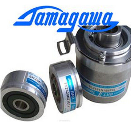
| Brand Name: | Tamagawa |
| Certification: | CE |
| Model Number: | TS5210N54 |
| Minimum Order Quantity: | 1pcs |
|---|---|
| Packaging Details: | carton |
| Delivery Time: | in stock |
| Payment Terms: | T/T, Western Union, MoneyGram |
| Supply Ability: | 100pcs/week |
| TAMAGAWA: | TAMAGAWA | TS5210N54: | TS5210N54 |
|---|---|---|---|
| Japan: | Japan | Material: | Iron |
| Color: | Black | Temperature: | 40-80 |
| Wire: | Wire | Dimension: | 40mm |
![]()
![]()
![]()
![]()
| lways takes a fixed amount of time to complete a scan cycle. In the event that the CPU does not complete the scan cycle in the specified minimum cycle |
following table defines the ranges and defaults for the cycle time monitoring functions. |
| time, the CPU completes the scan normally (including communication processing) and does | The maximum scan cycle time is always enabled. Configure a cycle time between 1 ms to 6000 ms |
| not create any system reaction as a result of exceeding the minimum scan time. | see "Monitoring the cycle time". (Page 80) The CPU provides the following memory areas to store the user program, data, and |
TS3103N156
TS5210N54
60798024
TS3653N2E6
TS5787N10
TS3624N3E6
TS-5008-N-65
TS2641N31E64
TS3741N3E8
TS1981N134E9
610568-1A
TS3653N3E7
TS5850N60
TS3630N1303E9
TS5008N66
TS2650N1E78
TS374
TS1981N53E19
61347
TS3653N3E8
TS5850N64
TS3630N1309E5
TS5010N
TS2650N11E78
Load memory is non-volatile storage for the user program, data and configuration. When
a project is downloaded to the CPU, it is first stored in the Load memory area. This area
is located either in a memory card (if present) or in the CPU. This non-volatile memory
area is maintained through a power loss. The memory card supports a larger storage
space than that built-in to the CPU.
● Work memory is volatile storage for some elements of the user project while executing
the user program. The CPU copies some elements of the project from load memory into
work memory. This volatile area is lost when power is removed, and is restored by the
CPU when power is restored.
● Retentive memory is non-volatile storage for a limited quantity of work memory values.
The retentive memory area is used to store the values of selected user memory locations
during power loss. When a power down or power loss occurs, the CPU restores these
retentive values upon power up.
To display the memory usage for the current project, right-click the CPU (or one of its blocks)
and select "Resources" from the context. To display the memory usage for the current CPU,
double-click "Online and diagnostics", expand "Diagnostics", and select "Memory". Data loss after power failure can be avoided by marking certain data as retentive. The
following data can be configured to be retentive:
● Bit memory(M): You can define the precise width of the memory for bit memory in the
PLC tag table or in the assignment list. Retentive bit memory always starts at MB0 and
runs consecutively up through a specified number of bytes. Specify this value from the
PLC tag table or in the assignment list by clicking the "Retain" toolbar icon. Enter the
number of M bytes to retain starting at MB0.
● Tags of a function block (FB): If an FB was created with "Optimzed" selected, then the
interface editor for this FB includes a "Retain" column. In this column, you can select
either "Retentive", "Non-retentive", or "Set in IDB" individually for each tag. An instance
DB that was created when this FB is placed in the program editor shows this retain
column as well. You can only change the retentive state of a tag from within the instance
DB interface editor if you selected "Set in IDB" (Set in instance data block) in the Retain
selection for the tag in the optimized FB.
If an FB was created with "Standard - compatible with S7-300/400" selected, then the
interface editor for this FB does not include a "Retain" column. An instance DB created
when this FB is inserted in the program editor shows a "Retain" column which is available