|
| Place of Origin: | Japan |
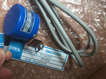
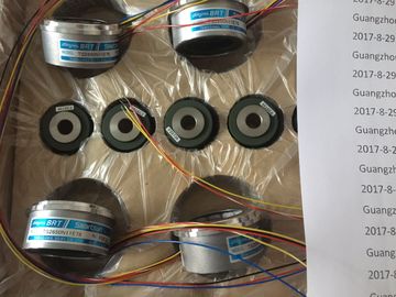
| Brand Name: | Tamagawa |
| Certification: | CE |
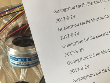
| Model Number: | TS5778N155 |
| Minimum Order Quantity: | 1pcs |
|---|---|
| Packaging Details: | carton |
| Delivery Time: | in stock |
| Payment Terms: | T/T, Western Union, MoneyGram |
| Supply Ability: | 100pcs/week |
| Tamagawa: | Tamagawa | TS5778N155: | TS5778N155 |
|---|---|---|---|
| COLOR: | BLACK | Japan: | Japan |
| Material: | Iron | Temperature: | 20-80 |
| Wire: | Wire | Dimension: | 40mm |
| Isolated modules are used for: | |
| DC load circuits with a separate reference potential | |
| All AC load circuits |
TS3103N156
TS5778N155
TS3692N42
TS3699N112
TS3699N172
TS3699N232
TS3738N1E7
TS3738N1E7
TS3741N3E8
TS374
TS3762N15E4
TS4126N1017E235
TS4127N1017E215
TS4127N1017E235
TS4231N6E17
TS4231N6E17
TS4244N10E24
TS4244N3E24
TS4502N1000E200
TS4502N1202E200
TS4502N2000E100
TS4503N1000E200
TS4503N1007E200
TS4503N1022E100
TS4503N1022E200
Examples of load circuits with a separate reference potential:
-- DC load circuits whose sensors have different reference potentials (for
example, when grounded sensors are used far from the programmable
controller and equipotential bonding is not possible).
-- DC load circuits whose positive terminal (L+) is grounded (battery circuits).
Isolated Modules and Grounding Concept
You can use isolated modules, regardless of whether or not the reference potential
of the programmable controller is grounded.Shown in Figure 4-4 are the potentials of an configured with isolated input
and output modules.The parallel wiring of a digital output (rated load voltage 1L+) with another digital
output (rated load voltage 2L+) or a rated load voltage 3L+ is only possible using
series diodesIf the L+ supplies of the digital output modules and the L+ voltage connected in
parallel to the output are always the same (difference < 0.5 V), there is no need to
use diodes, see figure 4-6.Grounding in accordance with regulations and conscientiously implemented is the
prerequisite for proper functioning of a programmable controller.
Each individual ponent of the and of the controlled system must be
properly grounded.
Ground Connections
Low-resistance ground connections reduce the risk of electric shock in the event of
a short-circuit or faults in the system. Moreover, proper grounding (low-impedance
connections: large surface area, wide-area bonding) together with the effective
shielding of lines and devices reduces the effect of interference on the system and
the interference signal emissions.
Note
Always ensure that operating currents do not flow via ground.
Protective Ground
All equipment of Safety Class I and all large metal parts must be connected to the
protective ground. This is essential to ensure that the user of the installation is
reliably protected from electric shock.
Furthermore, this serves to discharge interference transferred via external power
supply cables, signal cables, or cables to I/O devices.
Shown in Table 4-2 are the grounding methods required for the individual
ponents.
Table 4-2 Methods of Protective GroundingCabinet/frame Connection to central ground point, e.g. ground bus, via
cable with protective conductor quality
Racks Connection to central ground point via cable with
10 mm2 min. cross-section, when racks are not installed in a
cabinet and not interconnected via large metal parts
Module None; automatically grounded via backplane bus when fitted
I/O device Grounded via power plug
Shields of connecting
cables
Connection to rack or central ground point (avoid ground
loops)
Sensors and actuators Grounding according to specifications applying to the
systemMany output modules require an additional load voltage to switch the actuators.
Two different modes are possible for this load voltage:
• Non-isolated operation
• Floating operation
The following table shows how the load voltage ground is connected in the
individual modes.
Table 4-3 Grounded connection load voltage
Mode Connection of Load Voltage
Non-isolated operation
• Grounded configuration