 |
| Place of Origin: | Japan |
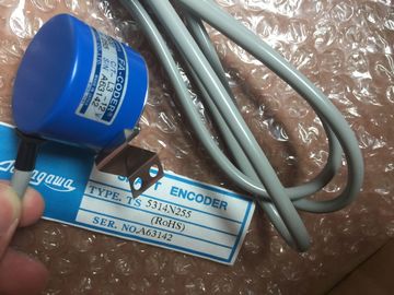
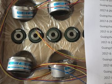
| Brand Name: | Tamagawa |
| Certification: | CE |
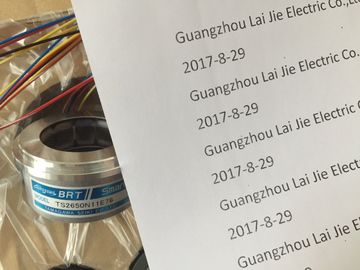
| Model Number: | TS2151N1E45 |
| Minimum Order Quantity: | 1pcs |
|---|---|
| Packaging Details: | carton |
| Delivery Time: | in stock |
| Payment Terms: | T/T, Western Union, MoneyGram |
| Supply Ability: | 100pcs/week |
| TAMAGAWA: | TAMAGAWA | Material: | Iron |
|---|---|---|---|
| Color: | Black | Temperature: | 20-80 |
| Wire: | Wire | Dimension: | 60mm |
| TS2151N1E45: | TS2151N1E45 |
TS3103N156
TS2151N1E45
TS3630N1306
TS3630N1E1
TS3630N1E2
TS3630N2E3
TS3630N2E4
TS3630N3E5
TS3630N101E2
TS3630N102E4
TS3630N22E3
TS3630N22E4
TS3631N1E1
TS3636N6
TS3641N1E1
TS3641N21E6
TS3641N22E7
TS3641N2E3
TS3641N12E3
TS3641N32
TS3641N38
TS3643N2
TS3643N212E5
TS3643N233E8
![]()
![]()
![]()
![]()
| Observe the ESD guidelines when installing interface submodules.. | |
| For this reason, you should always hold the interface submodules on the longest sides of the front panel. |
|
| The surface temperatures on the components can reach up to 70o C and there is a risk of burning. |
Slowly push the interface submodule into the slot until the front plate rests on
the frame of the card slot.
4. Important! Secure the front plate with the two fitted, captive M2.5 x 10 slot-head
screws on the left frame of the card slot.g Unused Submodule Slots
On delivery, all the submodule slots are secured with a submodule cover. The
cover is attached to the frame of the card slot with screws.
Leave unused submodule slots secur Insert the new backup battery/batteries in the battery compartment of the power
supply module.
Ensure correct polarity of the battery/batteries.
5. Switch on battery monitoring with the BATT INDIC slide switch.Discharge any static charge by touching a grounded metal part of the .
2. Open the cover of the power supply module.
3. Using the loop(s), pull the backup battery/batteries out of the battery
compartment.You should change the backup battery once a year.
Observe the usual regulations/guidelines for disposing of lithium batteries in your
country.
Backup batteries should be stored in a cool, dry place.
Backup batteries can be stored for ten years. If they are stored for a longer period,
however, a passivation layer may form.Risk of injury, material damage, release of hazardous substances.
Lithium batteries can explode if handled improperly. Their improper disposal may
result in the release of hazardous substances. Strictly adhere to the following instructions:
• Do not throw a new or low battery into an open fire and do not perform any soldering
work on the cell casing (max. temperature 100 °C). Do not recharge the
battery -- risk of explosion! Do not open a battery. Replace a faulty battery onoly
with the same type. Replacement batteries can be ordered from (for
order numbers, refer to the “Module data” reference manual, in appendix C)
his will insure that your are installing a short circuit-proof type.
• Always try to return low batteries to the manufacturer or deliver these to a registered
recycling companyIf you have provided the modules in your system with slot numbering, you must
remove the number from the old module when replacing it and apply the number to
the new module.Set the CPU mode switch to STOP.
When you replace the power supply module in an ER, the CR may remain in the
RUN state, depending on CPU programming. You can back up the data in the
ER via the EXT. BATT. socket of the receive IM.
2. If you wish to back up the data in the CPU, you can use the EXT. BATT. socket
of the CPU (see Reference Manual, Chapter 1).
3. Set the standby switch of the power supply module to (0 V output voltages).
4. Set the line disconnector to OFF.
5. Remove the cover.
6. Remove the backup battery/batteries if applicable.