 |
| Place of Origin: | Japan |
| Brand Name: | Tamagawa |
| Certification: | CE |
| Model Number: | TS5787N10 |
| Minimum Order Quantity: | 1pcs |
|---|---|
| Packaging Details: | carton |
| Delivery Time: | in stock |
| Payment Terms: | T/T, Western Union, MoneyGram |
| Supply Ability: | 100pcs/week |
| TAMAGAWA: | TAMAGAWA | TS5787N10: | TS5787N10 |
|---|---|---|---|
| Japan: | Japan | Material: | Iron |
| Color: | Black | Temperature: | 30-80 |
| Wire: | Wire | Dimension: | 50mm |
| Push the dummy plates in until the snap-in mechanism engages in the openings on the back of the cable routing. |
|
| Then install the fan assembly in the 19-inch pitch directly under the rack or between two racks. Use M6 size screws for mounting |
|
| The following figure shows how to mount the fan subassembly between two racks |
TS3103N156
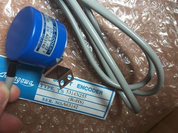
TS5787N10
TS1857
TS5607
TS5668N20
TS5667N120
TS5667N420
TS5645
TS5647
TS5648
TS5643
TS2223
TS2224
TS2225
TS20E12
TS13E11
TS5308N616
TS2650N11E78
TS5420N60
TS5208N131
TS3462N1E76
48-2500P8-L6-5VC/T-L3-12V
TS-5016N-60
Refit the left cover.
7. Secure the left cover with the quick-release lock.
Monitoring the Fan Subassembly
To monitor the functioning of the fan subassembly via your program, connect the
outputs to a digital module.
Further details on the monitoring concept can be found in the Reference Manual,
Chapter 91. Install the cable duct in the 19-inch pitch directly under the rack or between two
racks. Use M6 size screws for mounting.
The following figure shows how to mount the cable duct between two racks
With larger installations and in an environment subject to interference or pollution,
you can install the in cabinets. The requirements of UL/CSA are met, for
example, by an installation in cabinets.
Types and Dimensions of Cabinets
Observe the following criteria when selecting cabinet types and their dimensions:
• Ambient conditions at the point of installation of the cabinet
• Required clearances for the racks
• Total power dissipation of ponents contained by the cabinet
The ambient conditions at the point of installation of the cabinet (temperature,
humidity, dust, effects of chemicals, explosion hazard) govern the required degree
of protection of the cabinet (IP xx). Further information on degrees of protection
can be found in IEC 529 and DIN 40050.Table 2-1 provides an overview of the most mon types of cabinet. You will also
find the principle of heat removal, as well as the estimated, maximum achievable
power loss removal and the degree of protection.
Heat removal
primarily by natural
thermal
convection, small
portion via the
cabinet wall
Increased heat
removal through
increased air
movement
Heat removal only
through the
cabinet wall; only
low power
dissipation
permissible. Heat
accumulation
usually occurs in
the top of the
cabinet.
Heat removal only
through the
cabinet wall.
Forced ventilation
of the internal air
results in improved
heat removal and
prevention of heat
accumulation.
Heat removal
through exchange
between heated
internal air and
cold external air.
The increased
surface of the
folded-area
sectional wall of
the heat
exchanger and
forced circulation
of internal and
external air permit
good heat output.
Degree of
protection IP 20
Degree of
protection IP 20
Degree of
protection IP 54
Degree of
protection IP 54
Degree of
protection IP 54
Typical removable power dissipation under the following boundary conditions:
• Cabinet size 2200 x 600 x 600 mm
• Difference between external and internal temperature of the cabinet: 20° C (for other temperature
differences, you must refer to the temperature characteristics of the cabinet manufacturer)
up to 700 W up to 2700 W
(1400 W with very
fine filter)
up to 260 W up to 360 W up to 1700 WThe removable power dissipation from a cabinet is governed by the type of cabinet,
its ambient temperature, and the arrangement of equipment in the cabinet.
Figure 2-2 shows a diagram with guide values for the permissible ambient
temperature of a cabinet measuring 600 x 600 x 2000 mm as a function of power
dissipation. These values only apply if you observe the specified installation
dimensions and clearances for racks. Further information can be found in
catalogs NV21 and ET1.
Figure 2-2 Max. Cabinet Ambient Temperature as a Function of Power Dissipation of
Equipment in the Cabinet
Legend for Figure 2-2:
1. Closed cabinet with heat exchanger;
heat exchanger size 11/6 (920 x 460 x 111 mm)
2. Cabinet with through-ventilation by natural convection
3. Closed cabinet with natural convection and forced circulation by equipment fansRisk of damage to the modules.
Modules may be damaged as a result of excess ambient temperature.The example below clarifies the maximum permissible ambient temperature at a
particular power loss for various cabinet types.
Equipment suitable for installation in a cabinet:
1 central rack 150 W
2 expansion racks, 150 Watts each 300 W
1 load current power supply under full load 200 W
Accumulated power loss 650 W