 |
| Place of Origin: | Japan |
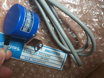
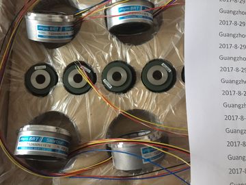
| Brand Name: | Tamagawa |
| Certification: | CE |
| Model Number: | TS2025N471E69 |
| Minimum Order Quantity: | 1pcs |
|---|---|
| Packaging Details: | carton |
| Delivery Time: | in stock |
| Payment Terms: | T/T, Western Union, MoneyGram |
| Supply Ability: | 100pcs/week |
| TAMAGAWA: | TAMAGAWA | Material: | Iron |
|---|---|---|---|
| Color: | Black | Japan: | Japan |
| TS2025N471E69: | TS2025N471E69 | Temperature: | 30-80 |
| Wire: | Wire | Dimension: | 50mm |
| Permissible ambient temperatures at an accumulated power loss as shown in Figure 2-2: |
(Curve 3) (no operation possible) |
| Type of Cabinet Max. Permissible Ambient | pen, with through-ventilation (Curve 2) approx. 38° C |
| Temperature Closed, with natural convection and forced circulation |
Closed, with heat exchanger (Curve 1) approx. 45° CVital dimensional design factors for an cabinet |
TS3103N156Temperature
Closed, with natural convection and forced circulation
TS2025N471E69
TS2225
TS20E12
TS13E11
TS5308N616
TS2650N11E78
TS5420N60
TS5208N131
TS3462N1E76
48-2500P8-L6-5VC/T-L3-12V
TS-5016N-60
TS5214N561
TS5214N510
TS2014N182E32
TS3653N2E5
TS5320N510
TS5016N-60
TS5016N60
TS5305N616
TS5008N12238
TS5214N564
TS5212N569
TS2651N111E78
TS2014N181E32
TS-5208N130
Space requirement of the racks
• Minimum clearance between racks and cabinet walls
• Minimum clearance between racks
• Space requirement of cable ducts or fan subassemblies
• Locations of railsYou only need to observe two rules for rack mounting of the modules:
• In all racks, the power supply module must always be inserted on the extreme
left (beginning with slot 1). In the UR2-H from slot 1 in both segments.
• The receive IM in the ER must always be inserted on the extreme right. In the
UR2-H at slot 9 once per segment.
Note
Establish whether there are additional regulations applying to all modules not
described in this manual.
The following table shows which modules can be used in the different racks:
Table 2-2 Modules in the different racksIn the system, there are modules occupying one, two, or three slots (width
25, 50, or 75 mm). Refer to the technical specifications of the module under the
keyword “dimensions” to see how many slots a module occupies.
The mounting depth of a rack fitted with modules is 237 mm maximum.All modules are installed using the same procedure.
! Caution
Modules and racks can be damaged.
Do not apply any undue force when installing the modules in a rack, because you
will more than likely damage the devices.
Carefully follow the steps described below for the installation sequence.
The tool needed to install the modules is a cylindrical screwdriver with 3.5 mm
blade width.
Installation Sequence
To install modules in a rack:
1. Remove the dummy plates from the slots at which you intend to insert modules.
Grasp the dummy plate at the points marked and pull it forward and off.
With double and triple-width modules, you must remove the dummy plates from
all the slots to be covered by the relevant module.
2. Remove the cover, if applicable, from the module (see Figure 2-3).
3. Disconnect the power supply connector at the power supply module.
4. Attach the first module and swing it downwards (see Figure 2-4).
If you feel a resistance when swinging the module down, raise it slightly and
Tighten the module screws top and bottom with a torque of 0.8 to 1.1 N/m (see
Figure 2-5). Triple-width modules are secured with two screws at the top and at
the bottom.
6. Refit the module cover, if applicable.
7. Fit the remaining modules in the same way.
The individual steps for installation are explained below.
The method of removing modules is described in Chapter 7.
Installing the
2-31 Automation System Hardware and Installation
A5E00850741-01
Removing the Cover
With modules which have a cover (for example, power supply modules and CPUs),
you remove this before installing the module in the rack. Proceed as follows:
1. Push the interlock lever down (1).
2. Swing the cover forward and off (2).Attach the modules one by one (1) and swing them carefully downwards (2). If you
feel a resistance when swinging the module down, raise it slightly and then
continue.Once the modules are installed, you should mark each one with its slot number to
avoid the risk of mixing up modules during operation. If modules do get mixed up,
you may have to reconfigure the assembly.
The slot number is printed on the rack.
Double-width modules occupy two slots and are assigned the consecutive slot
numbers of both slots.
Triple-width modules occupy three slots and are assigned the consecutive slot
numbers of these three slots.You use slot labels to mark a module with its slot number. The slot labels are
provided with the rack as a “number wheel”.
To attach the slot labels:
1. Hold the “number dial” on the module and rotate it to the slot number for the
module inserted at this slot.
2. Use your finger to press the slot label into the module. The label will break away
from the “number wheel”.Apart from the structures mentioned in this chapter, other expansions are possible,
for example, by connecting distributed I/Os or by networking.
Distributed I/Os
When an is configured with a distributed I/O system, the inputs/outputs
operate in a distributed local arrangement and are directly connected via
PROFIBUS DP to a CPU.
One of the master-capable CPUs of the is used.
You can use the following devices, for example, as slaves, i.e. as local
inputs/outputs:
then continue.