 |
| Place of Origin: | Japan |
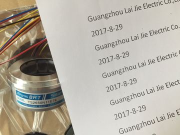
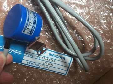
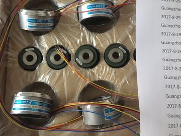
| Brand Name: | Tamagawa |
| Certification: | CE |
| Model Number: | TS5207N530 |
| Minimum Order Quantity: | 1pcs |
|---|---|
| Packaging Details: | carton |
| Delivery Time: | in stock |
| Payment Terms: | T/T, Western Union, MoneyGram |
| Supply Ability: | 100pcs/week |
| TAMAGAWA: | TAMAGAWA | TS5207N530: | TS5207N530 |
|---|---|---|---|
| Material: | Iron | Color: | Black |
| Wire: | Wire | Temperature: | 20-120 |
| Japan: | Japan | Dimension: | 60mm |
TS3103N156
TS5207N530
TS5016N64
TS5017N60
TS5019N60
TS5420N60
TS5778N155
TS5013N68
TS5013N69
TS5208N131
TS5208N23
TS2025N471E69
TS2014N181E32
TS5208N111E78
TS5208N141E78
TS5631N224
PULSE
GENERATOR
RP-182
750PPR
![]()
![]()
![]()
![]()
| Programming device | When operating thermocouples on analog input modules |
| A programming device (PG) is a special compact PC (Personal Computer) suitable for use in | point of known temperature (for example, → compensating box.) Reference potential |
| industry. A PG is fully equipped for programming SIMATIC automation systems. Reference junction |
Potential from which the voltages of participating circuits are derived and measured. |
Repeat accuracy
Denotes the maximum deviation between measured/output values, if the same input or
output signal is repeatedly set. Repeat accuracy refers to the rated range of the module, and
applies to its settled temperature state.
Glossary
S7-300 Module data
Manual, 06/2017, A5E00105505-AJ 635
Repeater
Equipment used to amplify bus signals, and couple → bus segments across greater
distances
Resolution
Number of bits representing the value of analog modules in binary format. The resolution is
module-specific. It is also determined by the → integration time of analog input modules. The
precision of the measured value resolution increases with the length of the integration time.
The maximum resolution is 16 bits + sign.
Response to open thermocouple
STEP 7 parameter for analog input modules operating with thermocouples. This parameter
defines whether the module outputs an "Overflow" (7FFFH) or "Underflow" (8000H) value
when it detects an open thermocouple.
Restart
At its restart (initiated by setting the mode selector switch from STOP to RUN, or after
POWER ON), the CPU first executes restart OB 100, and then continues with cyclic program
execution (OB1.)
During its restart, the CPU reads the → Process image of inputs (PIO), and then executes
the STEP 7 user program, starting at the first statement in OB1.
Retentivity
Data areas in data blocks (DBs), timers, counters and flags are considered retentive if their
content is not lost as a result of restart or power off.
Scaling
STEP 7 parameter for the SM 338; POS-INPUT position detection module. Scaling rightaligns
the → Absolute encoder value in the address space; irrelevant places are discarded.
Segment
→ Bus segment
SFC
→ System Function
Signal module
Signal modules (SMs) form the interface between the process and the automation system.
These are available as digital and analog input/output and IO modules.STEP 7 parameter for analog input modules. The measured values are smoothed by digital
filtering. Users can select module-specific filter properties, i.e. none, low, medium or high.
The time constant of the digital filter increases in proportion to the degree of smoothing.
STARTUP
STARTUP mode initiates the transition from STOP to RUN mode. STARTUP can be
triggered by setting the → mode selector, by power on, or by an operator action on the
programming device. S7-300 performs a → restart.
Substitution value
Values output by faulty signal output modules to the process, or used to substitute a process
value of a faulty signal input module in the user program.
Users can program the substitute values in STEP 7 (hold last value, substitution value 0 or
1.) Those values must be set at the outputs when the CPU goes into STOP.Denotes the detection, evaluation and reporting of error events within the automation
system. Examples of such errors are: program errors, or module failure. System errors may
be indicated by LED displays, or in STEP 7.
System Function
A System Function (SFC) is an integral function of the CPU operating system, and can be
called in the STEP 7 user program as required.
Temperature coefficient
STEP 7 parameter for analog input modules, for temperature measurements taken with
resistance thermometers (RTD.) The selected temperature coefficient is specific to the
resistance thermometer being used (to DIN standard.)
Temperature error
Denotes the drift of measured/output values, caused by fluctuation of the ambient
temperature at an analog module. It is defined in % per Kelvin, relative to the rated range of
the analog module