|
| Place of Origin: | Japan |
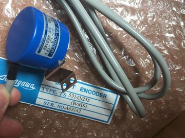
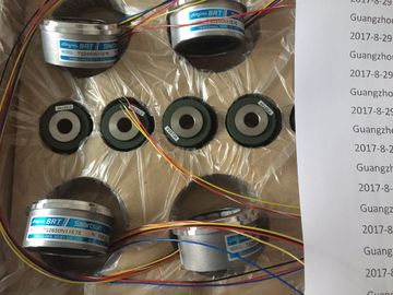
| Brand Name: | Tamagawa |
| Certification: | CE |
| Model Number: | TS5013N60 |
| Minimum Order Quantity: | 1pcs |
|---|---|
| Packaging Details: | carton |
| Delivery Time: | in stock |
| Payment Terms: | T/T, Western Union, MoneyGram |
| Supply Ability: | 100pcs/week |
| TAMAGAWA: | TAMAGAWA | Temperature: | Color |
|---|---|---|---|
| Material: | Iron | WIRE: | Wire |
| Dimension: | 50mm | Japan: | Japan |
| Color: | Black | TS5013N60: | TS5013N60 |
| Reserve MPI address “2” for a new CPU. | setting has been installed in the MPI network (for example, when replacing a CPU). Thus you assign an MPI address higher than “2” to all CPUs in the MPI network. |
| Reserve MPI address “2” for a new CPU. | |
| You thus avoid the duplication of MPI addresses after a CPU with a default s |
setting has been installed in the MPI network (for example, when replacing a CPU). Thus you assign an MPI address higher than “2” to all CPUs in the MPI network. |
TS3103N156
TS5013N60
TS3653N58E5
TS3653N65E27
TS3653N81E27
TS3653N78E5
TS3653N94E5
TS3653N181E8
TS3658N3
TS3664N1E1
TS3664N1E2
TS3664N2E3
TS3664N2E4
TS3664N50
TS3664N50
TS3667N1E2
TS3667N11E2
TS3667N2E5
TS3667N2E6
TS3667N3E7
TS3667N3E8
TS3667N13E8
TS3674N37
TS3679N2E1
Before you interconnect the individual nodes of the network, you must assign to
each node the MPI address and the highest MPI address or PROFIBUS-DP
address.
Tip: Mark the address of each node in a network on the housing. To do this, use
the adhesive labels enclosed with the CPU. You can then always see which
address is assigned to which node in your plant.
• Before you insert a new node in the network, you must switch off its supply
voltage.
• Connect all the nodes in the network in a row. In other words, include the fixed
programming devices and operator panels directly in the network.
Only use spur lines for connecting the programming devices / OPs to the
network which are needed for startup or maintenance.
• If you operate more than 32 nodes in a PROFIBUS-DP network, you must
connect the bus segments via RS 485 repeaters.
In a PROFIBUS-DP network, all bus segments together must have at least one
DP master and one DP slave.
• You connect ungrounded bus segments and grounded bus segments via
RS 485 repeaters (see Reference Manual CPU Data, Chapter 10).
• The maximum number of nodes per bus segment decreases with each
RS 485 repeater. This means that if there is an RS 485 repeater in a bus
segment, there may only be a maximum of 31 other nodes in a bus segment.
However, the number of RS 485 repeaters has no effect on the maximum
number of nodes on the bus.
Up to ten segments can be connected in series.
• Switch on the terminating resistor at the first and last node of a segment.
To ensure the bus operates without interference, you should not switch off these
nodes.
Observe the following feature in the MPI network:
Note
If you connect an additional CPU to the MPI network during operation, data may
be lost.
Remedy:
1. Disconnect power from the nodes to be connected.
2. Connect the nodes to the MPI network.
3. Switch on the nodes.
Recommendation for MPI Addresses
Reserve MPI address “0” for a service programming device and “1” for a service
OP, which will later be briefly connected to the MPI network as required. Thus you
assign different MPI addresses to the programming devices / OPs incorporated in
the MPI network.