|
| Place of Origin: | Japan |
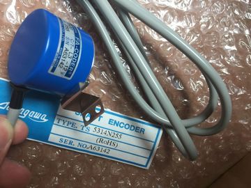
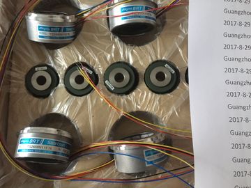
| Brand Name: | Tamagawa |
| Certification: | CE |
| Model Number: | TS5208N68 |
| Minimum Order Quantity: | 1pcs |
|---|---|
| Packaging Details: | carton |
| Delivery Time: | in stock |
| Payment Terms: | T/T, Western Union, MoneyGram |
| Supply Ability: | 100pcs/week |
| TAMAGAWA: | TAMAGAWA | TS5208N68: | TS5208N68 |
|---|---|---|---|
| Material: | Iron | Color: | Black |
| Temperature: | 30-80 | Dimension: | 50mm |
| Wire: | Wire | Japan: | Japan |
![]()
![]()
![]()
![]()
| Recommendation for PROFIBUS-DP Addresses | |
| Thus you assign other PROFIBUS-DP addresses to all the programming devices |
|
| Reserve PROFIBUS-DP address “0” for a service programming device, which will later be briefly connected to the PROFIBUS-DP network as required. |
TS5208N68
TS3684N1E3
TS3684N2E6
TS3684N3E8
TS3692N103
TS3692N41
TS3692N42
TS3699N112
TS3699N172
TS3699N232
TS3738N1E7
TS3738N1E7
TS3741N3E8
TS374
TS3762N15E4
TS4126N1017E235
TS4127N1017E215
TS4127N1017E235
TS4231N6E17
TS4231N6E17
TS4244N10E24
TS4244N3E24
TS4502N1000E200
TS4502N1202E200
incorporated in the PROFIBUS-DP network.
Components
You connect the individual nodes via bus connectors and the PROFIBUS-DP bus
cable. Remember to provide a bus connector with PG female port for nodes into
which a programming device may be plugged if required.
Use RS 485 repeaters for the connection between segments and for extending the
cable.
The figure below shows where you have to connect the terminating resistor in a
possible configuration for an MPI networThe figure below shows an example of a configuration with CPU 414-2 DP which is
integrated in an MPI network and simultaneously used as DP master in a
PROFIBUS-DP network.
In both networks, the node numbers can be assigned separately without conflicts
resultingFigure 5-9 Programming device access beyond network limits
Requirements :
• Use STEP 7 from version 5.0 onwards
• Assign STEP 7 to a programming device or PC on the network
(SIMATIC Manager, Assign programming device/PC)
• The network limits are bridged by modules with routing capability
In a segment of an MPI network, you can use cable lengths of up to 50 m. This
50 m applies from the first node to the last node in the segment.
Table 5-1 Permitted Cable Length of a Segment in an MPI Network
If you have to implement cable lengths which are longer than permissible in one
segment, you must interconnect RS 485 repeaters. The maximum possible cable
length between two RS 485 repeaters is the same as the cable length of a segment
(see Tables 5-1 and 5-2). With these maximum cable lengths, however, note that
no other nodes may be situated between the two RS 485 repeaters. You can
connect up to ten RS 485 repeaters in series.
Note that you must count an RS 485 repeater as a node of the MPI network in the
total number of all nodes to be connected, even if it is not assigned its own
MPI number. The use of RS 485 repeaters reduces the number of nodes
If you do not fit the bus cable directly at the bus connector (for example, when
using a PROFIBUS-DP bus terminal), you must take into account the maximum
possible spur line length.
The following table gives the maximum lengths of spur lines allowed per bus
segment:
A spur line is not permissible with transmission rates greater than 1.5 Mbps.
To connect a programming device or PC, use the connecting cable for the
programming with theorder number 6ES7901-4BD00-0XA0. You can use several
connecting cable with this order number for programming devices in one bus
configuration.
The figure below shows a possible configuration of an MPI network. This example
clarifies the maximum possible distances in an MPI network.The PROFIBUS-DP bus cable is a twisted, shielded pair with the following
characteristics:
Characteristics Values
Impedance approx. 135 to 160 Ω (f = 3 to 20 MHz)
Loop resistance ≦ 115 Ω/km
Working capacitance 30 nF/km
Attenuation 0.9 dB/100 m (f = 200 kHz)
Permissible core cross-section 0.3 mm2 to 0.5 mmFor detailed information on how to connect a bus cable to a bus connector, refer to
the SIMATIC NET Profibus Networks manual.
Connecting the Bus Connector
To connect the bus connector, proceed as follows:
1. Plug the bus connector into the module.
2. Screw the bus connector into the module.
3. If the bus connector is located at the beginning or end of a segment, you must
switch on the terminating resistor.
Figure 5-12 Switch on terminating resistant
Ensure that power is always applied to the stations at which the terminating resistor
is situated, during startup and operation.
Removing the Bus Connector
With a looped-through bus cable you can remove the bus connector from the
PROFIBUS-DP interface at any time, without interrupting data traffic on the bus.
! Warning
Interference to the data traffic on the bus is possible.