|
| Place of Origin: | Japan |
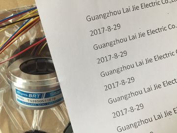
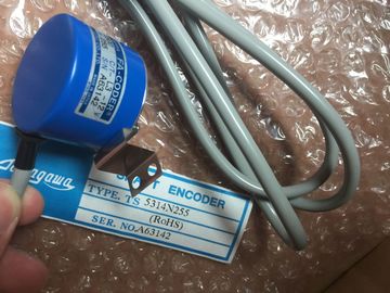
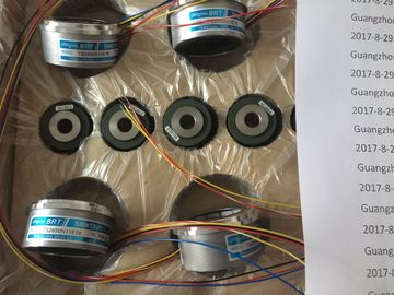
| Brand Name: | Tamagawa |
| Certification: | CE |
| Model Number: | TS5210N450 |
| Minimum Order Quantity: | 1pcs |
|---|---|
| Packaging Details: | carton |
| Delivery Time: | in stock |
| Payment Terms: | T/T, Western Union, MoneyGram |
| Supply Ability: | 100pcs/week |
| TAMAGAWA: | TAMAGAWA | Temperature: | 20-70 |
|---|---|---|---|
| Color: | Black | TS5210N450: | TS5210N450 |
| Wire: | Wire | Material: | Iron |
| Dimension: | 50mm |
TS3103N156
TS5210N450
TS4127N1017E215
TS4127N1017E235
TS4231N6E17
TS4231N6E17
TS4244N10E24
TS4244N3E24
TS4502N1000E200
TS4502N1202E200
TS4502N2000E100
TS4503N1000E200
TS4503N1007E200
TS4503N1022E100
TS4503N1022E200
TS4503N1202E200
TS4503N1205E200
TS4503N1828E100
TS4503N2000E100
TS4503N2070E100
TS4503N2202E200
TS4503N2036E501
TS4506N1202E200
TS4507N1002E200
![]()
![]()
![]()
![]()
| A bus segment must always be terminated with the terminating resistor at both ends. This is not the case, |
|
| or example, when the last slave with bus connector is not under power. Since the bus connector is powered by the station, |
|
| the terminating resistor has no effect. |
Ensure that the stations at which the terminating resistor is switched on are always
under power.The RS 485 Repeater / Diagnostics Repeater amplifies data signals on bus cables
and couples bus segments.
You need an repeater when:
• More than 32 nodes are connected in the network,
• A grounded segment is to be connected to an ungrounded segment
• The maximum cable length of a segment is exceeded.
Description of the RS 485 Repeater
A detailed description and technical data of the RS 485 repeater can be found in
the Reference Manual Module Specifications, Chapter 10.
Assembly
You can install the repeater on a 35 mm standard profile rail.
Wiring the Power Supply Unit
To wire the power supply unit of the repeater, proceed as follows:
1. Open the “M” and “PE” screws.
2. Strip the 24 VDC power supply cable.
3. Terminate the cable to “L+” and “M” or “PE”.
Terminal “M5.2”
Terminal “M5.2” should not be wired because it is only needed during maintenance.
Terminal “M5.2” is the reference ground you require when measuring the voltage
between terminals “A1” and “B1”.
Connecting the PROFIBUS-DP Bus Cable
For detailed information on hwo to connect the PROFIBUS DP bus cable to the
RS 485 repeater, refer to the SIMATIC NET Profibus Networks manual:If you want to use the field bus for larger distances irrespective of the transmission
rate, or if the data traffic on the bus is not to be impaired by external interference
fields, use fiber-optic cables rather than copper cables.
There are two ways to convert electrical cables to fiber-optic cables:
• PROFIBUS nodes with a PROFIBUS-DP interface (RS 485) are connected to
the optical network via an Optical Bus Terminal (OBT) or via the Optical Link
Module (OLM).
• PROFIBUS nodes with an integrated fiber-optic cable interface (e.g. ET 200M
(IM 153-2 FO), (IM 467 FO)) can be directly integrated in the optical
network.
How to set up optical networks with the Optical Link Module (OLM) is described in
detail in the SIMATIC NET PROFIBUS Networks manual. You will find below the
most important information on setting up an optical PROFIBUS-DP network with
PROFIBUS nodes that have an integrated fiber-optic cable interface.
Benefits and Areas of Application
Fiber-optic cables have the following advantages over electrical cables:
• Electrical isolation of the PROFIBUS-DP components
• Insensitivity to electromagnetic interference (EMC)
• No electromagnetic emission into the environment
• Thus no need for additional grounding and shielding measures
• No adherence to minimum clearances from other cables necessary for EMC
No need for equipotential bonding conductors
• No need for lightning conductors
• Maximum permissible cable lengths independent of the transmission rate
• Easy installation of the fiber-optic cable connections of the PROFIBUS-DP
components by means of standard fiber-optic cable connectors (Simplex
connectors)sion Rate
The following transmission rates are possible when the optical PROFIBUS-DP
network is operated with a partyline topology:
A PROFIBUS node can be connected to the optical PROFIBUS-DP network via a
PROFIBUS Optical Bus Terminal (OBT) (6GK1 500-3AA00) without an integrated
fiber-optic cable interface (e.g. programming devices (PGs) or operator panels
(OPs), see Figure 5-13).
The programming device/PC is connected to the RS 485 interface of the OBT by
means of the PROFIBUS cable. The OBT is integrated in the optical
PROFIBUS-DP line by means of its fiber-optic cable interface.
SIMATIC NET PROFIBUS PCF fiber-optic, standard cable
I-VY2K 200/230 10A17 + 8B20
PCF fiber-optic cable with 2 conductors, PVC outer sheath, fitted
with 4 Simplex connectors, whip length 30 cm each, for distances
up to 300 m
(Other lengths on request)
Simplex connectors allow you to connect the fiber-optic cable to the integrated
fiber-optic cable interface on the PROFIBUS device. In some modules (e.g.
IM 153-2 FO, IM 467 FO) two Simplex connectors (one for the sender and one for
the receiver) are inserted in the module by means of a special connector adapter.
Prerequisite
The PROFIBUS device must be equipped with a fiber-optic cable interface, such as
the ET 200M (IM153-2 FO) or the IM 467 FO for
e
Two Simplex connectors (a sender and a receiver) and a connector adapter with
the following attributes are required for a fiber-optic cable connection:
• Degree of protection IP20
protection
• Transmission rate 9.6 kbps to 12 MbpsSIMATIC NET PROFIBUS plastic fiber-optic Simplex