|
| Place of Origin: | Japan |
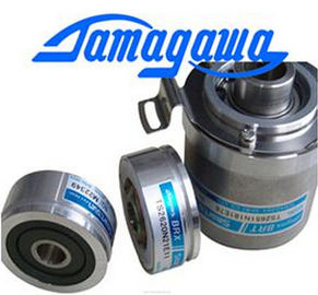
| Brand Name: | Tamagawa |
| Certification: | CE |
| Model Number: | TS5013N61 |
| Minimum Order Quantity: | 1pcs |
|---|---|
| Packaging Details: | carton |
| Delivery Time: | in stock |
| Payment Terms: | T/T, Western Union, MoneyGram |
| Supply Ability: | 100pcs/week |
| TAMAGAWA: | TAMAGAWA | Material: | Iron |
|---|---|---|---|
| Color: | Black | Temperature: | 20-80 |
| Wire: | Wire | TS5013N61: | TS5013N61 |
| Dimension: | 50mm |
TS3103N156
TS5013N61
TS1508N260
TS1613N200
TS16N13E12
TS16N18E11
TS2013N191E26
TS2014N181E32
TS2014N311E32
TS2014N312E32
TS2018N303E51
TS20E12
TS20N2E11
TS2142N1E63
TS2151N1E26
TS2151N1E45
TS2151N11E45
TS2640N321E64
TS2641N31E64
TS2650N1E78
TS2650N11E78
TS2650N101E78
TS2651N111E78
TS2651N181E78
| connector/polishing set | with connectorsConnector adapters |
| 100 Simplex connectors and 5 polishing sets for fitting | Pack of 50 for fitting plastic Simplex connectors with |
| SIMATIC NET PROFIBUS plastic fiber-optic cables | the IM 467 FO and the IM 153-2 FOWith fiber-optic cables, the length of the cable segment does not depend on the |
the IM 467 FO and the IM 153-2 FOWith fiber-optic cables, the length of the cable segment does not depend on theransmission rate.
Each bus node in the optical PROFIBUS-DP network has repeater functionality.
The distances specified below are the distances between two neighboring
PROFIBUS nodes in the partyline topology.
The maximum cable length between two PROFIBUS nodes depends on the type of
the fiber-optic cable used.
Table 5-7 Permissible Cable Lengths on the Optical PROFIBUS-DP Network (Partyline
Topology)e of Plastic Fiber-Optic and PCF Fiber-Optic Cable
To gain the maximum benefit from the different cable lengths you can mix the
plastic and PCF fiber-optic cables.
For example, you can use plastic fiber-optic cable for connections between DP
slaves locally (distances <50 m) and PCF fiber-optic cable for the connection
between the DP master and the first DP slave in the partyline topology (distance
>50 m).
Laying PCF Fiber-Optic Cable
You can order PCF fiber-optic cables fitted with 2x2 connectors in specific lengths
from .
Lengths and order numbers: See Table 5-5
Laying Plastic Fiber-Optic Cable
You can easily fit connectors to and install plastic fiber-optic cables yourself. Please
read the following information on how to do this and on the rules for laying the
cable.Here you will find detailed installation instructions and a series of photographs on
fitting plastic fiber-optic cables with Simplex connectors:
• In the appendix of the SIMATIC NET PROFIBUS Networks manual
• On the InternetClick SEARCH on this page, enter the number “574203” under “Entry-ID” and
start the search function.
• Enclosed with the Simplex connector/polishing set
Title: Assembly instructions for SIMATIC NET PROFIBUS Plastic Fiber Optics with
Simplex connectors
r Laying Cable
When you lay plastic fiber-optic cable, please adhere to the following rules:
• Use only the fiber-optic cables specified in Section 5.8.1
• Never exceed the maximum permissible stresses (tensile load, crushing, etc.) of
the cable you are using specified in Table 5-4. Impermissible crushing can
occur, for example, when screw clamps are used to fix the cable in place.
• Follow the steps specified in the installation instructions, and use only the tools
specified there. Grind and polish the fiber ends carefullyNote
Polishing the fiber ends of the fiber-optic cable, as described in the installation
instructions, reduces attenuation by 2 dB.
• Grind and polish by pressing the connector only lightly against the abrasive
paper or polishing foil in order to prevent the connector fusing with the fiber.
• Ensure that you maintain the bend radii specified in Table 5-4 during grinding
and polishing, particularly when cables are supported for mechanical strain
relief. In this case, ensure an adequate whip length.
• Ensure that there are no loops when cables are cut to length. Under tensile
load, loops can cause kinks to form in the cable and thus damage it.
• Ensure that the outer and conductor sheathing of the cable and the fibers are
not damaged. Scoring and scratches can let light escape and thus lead to
higher attenuation values and line failure.