|
| Place of Origin: | Japan |
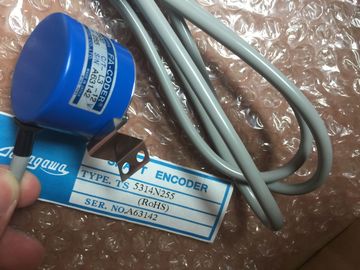
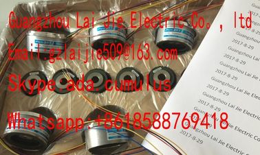
| Brand Name: | Tamagawa |
| Certification: | CE |
| Model Number: | TS5212N351 |
| Minimum Order Quantity: | 1pcs |
|---|---|
| Packaging Details: | carton |
| Delivery Time: | in stock |
| Payment Terms: | T/T, Western Union, MoneyGram |
| Supply Ability: | 100pcs/week |
| TAMAGAWA: | TAMAGAWA | TS5212N351: | TS5212N351 |
|---|---|---|---|
| COLOR: | BLACK | Japan: | Japan |
| Material: | Iron | Temperature: | 20-80 |
| Wire: | Wire | Dimension: | 50mm |
| You can install the CPU on a panel or on a DIN rail. Note Attach any communication modules to the CPU and install the assembly as a unit. Install |
For DIN rail mounting, make sure the upper DIN rail clip is in the latched (inner) position |
| signal modules separately after the CPU has been installed. | |
| Consider the following when installing the units on the DIN rail or on a panel: |
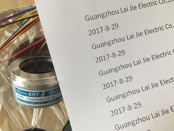
TS5212N351
TS5000N632
TS5003N632
TS5005N122
TS5007N122
TS5007N635
TS5208N500
TS5208N510
TS5208N530
TS5208N569
TS5208N576
TS5210N450
TS5210N453
TS5210N458
TS5210N530
TS5210N54
TS5210N553
TS3684N1E3
and that the lower DIN rail clip is in the extended position for the CPU and attached CMs.
● After installing the devices on the DIN rail, move the lower DIN rail clips to the latched
position to lock the devices on the DIN rail.
● For panel mounting, make sure the DIN rail clips are pushed to the extended position.
To install the CPU on a panel, follow these steps:
1. Locate, drill, and tap the mounting holes (M4), using the dimensions shown in table,
Mounting dimensions (mm) (Page 46).
2. Ensure that the CPU and all equipment are disconnected from electrical power.
3. Extend the mounting clips from the module. Make sure the DIN rail clips on the top and
bottom of the CPU are in the extended position.
4. Secure the module to the panel, using a Pan Head M4 screw with spring and flat washer.
Do not use a flat head screw. The type of screw will be determined by the material upon which it is mounted. You
should apply appropriate torque until the spring washer becomes flat. Avoid applying
excessive torque to the mounting screws. Do not use a flat head screw.
Note
If your system is subject to a high vibration environment, or is mounted vertically, panel
mounting the will provide a greater level of protection. 1. Install the DIN rail. Secure the rail to the mounting panel every 75 mm.
2. Ensure that the CPU and all equipment are disconnected from electrical
power.
3. Hook the CPU over the top of the DIN rail.
4. Pull out the DIN rail clip on the bottom of the CPU to allow the CPU to fit over the
rail.
5. Rotate the CPU down into position on the rail.
6. Push in the clips to latch the CPU to the rai1. Install the DIN rail. Secure the rail to the mounting panel every 75 mm.
2. Ensure that the CPU and all equipment are disconnected from electrical
power.
3. Hook the CPU over the top of the DIN rail.
4. Pull out the DIN rail clip on the bottom of the CPU to allow the CPU to fit over the
rail.
5. Rotate the CPU down into position on the rail.
6. Push in the clips to latch the CPU to the rai1. Ensure that the CPU and all equipment are disconnected
from electrical power.
2. Remove the top and bottom terminal block covers from the CPU.
3. Place a screwdriver into the slot on top of the CPU at the rear of the
cover.
4. Gently pry the cover up and remove it from the CPU.
5. Place the module straight down into its mounting position in the top
of the CPU.
6. Firmly press the module into position until it snaps into place.
7. Replace the terminal block covers. 1. Ensure that the CPU and all equipment are disconnected
from electrical power.
2. Remove the top and bottom terminal block covers from the CPU.
3. Place a screwdriver into the slot on top of the module.
4. Gently pry the module up to disengage it from the CPU.