|
| Place of Origin: | Japan |
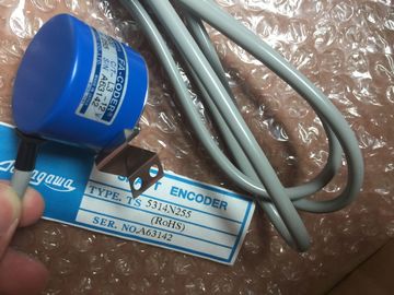
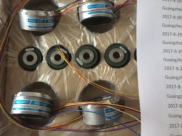
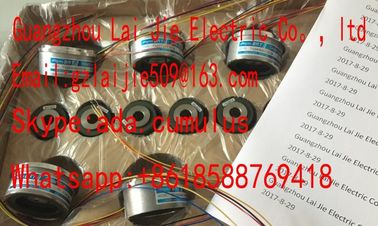
| Brand Name: | Tamagawa |
| Certification: | CE |
| Model Number: | TS5210N453 |
| Minimum Order Quantity: | 1pcs |
|---|---|
| Packaging Details: | carton |
| Delivery Time: | in stock |
| Payment Terms: | T/T, Western Union, MoneyGram |
| Supply Ability: | 100pcs/week |
| TAMAGAWA: | TAMAGAWA | JAPAN: | JAPAN |
|---|---|---|---|
| Color: | Black | Material: | Iron |
| Temperature: | 20-80 | TS5210N453: | TS5210N453 |
| Never insert dirty connectors or connectors with protruding fibers in the device sockets. This can destroy the optical sending and receiving elements. |
very extensive and complex. A first startup of an with two or more racks and all modules inserted is therefore not advisable. Instead, a startup in stages is recommended. |
| Installing the Connector Adapter | When commissioning an H system, you should first start up each subsystem separately, as described in this chapter, |
| The installation of the cut fiber-optic cable with connector on the PROFIBUS devices is module-specific, |
and it is therefore described in the manual for the PROFIBUS device with an integrated fiber-optic cable interfaceDue to the modular assembly and the many expansion options, an can be |
TS3103N156
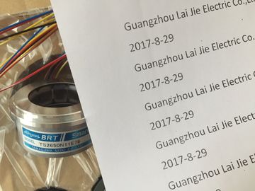
TS5210N453
TS5210N453
TS5210N458
TS5210N530
TS5210N54
TS5210N553
TS3684N1E3
TS3684N2E6
TS3684N3E8
TS3684N11E3
TS3684N12E6
TS3684N13E8
TS3617N1E3
TS3617N1E1
TS3617N1E2
TS3617N2E4
TS3617N2E5
TS3617N2E6
TS3617N2E7
TS3617N3E8
TS3617N3E9
before connecting both subsystems
together to form a complete system.
The following procedure is recommended for the first startup of an :
1. Carry out the checks listed in Table 6-1.
2. First start the CR with the power supply module and CPU inserted (see
Section 6.4). If you are installing an in a segmented rack, you must
insert both CPUs for the preliminary commissioning phase.
Check the LED indicators on the two modules. The meanings of these LED
indicators can be found in the Reference Manual Module Specifications,
Chapter 3 and in the reference manual CPU Data.
. Insert additional modules in the CR, one at a time, and start them up one at a
time.
4. If required, connect the CR to ERs by inserting one or more send IMs in the CR
and the matching receive IM in the ER.
In the case of ERs with their own power supply modules, switch them on first
and then the power supply module of the CR.
5. Insert additional modules in the ERs one at a time and start them up one after
the other.If an error occurs, you can proceed as follows:
-- Check your system by means of the checklist in Section 6.2.
-- Check the LED indicators on the modules. Meanings of these indicators can
be found in the chapters containing the descriptions of the relevant modules.
-- If necessary, remove individual modules to locate faults.
After installing and wiring your , it is advisable to check the steps carried out
so far, before switching on for the first time.
Table 6-1 contains a guide in the form of a checklist for your , and refers to
the chapters containing additional information on the subject.
Table 6-1 Checklist to be Used Before Switching On for the First TimeAre the racks secured on the wall, in
the frame or cabinet?
Have the necessary clearances been
allowed?
2
Are cable ducts or fan subassemblies
correctly installed?
2
Is the ventilation in order? 2
Grounding and Chassis Ground Concept
Is there a low-impedance connection
(large surface, large-area contact) to
the chassis ground?
2
On all racks, is the connection between
reference ground and chassis
ground correct (metallic connection or
ungrounded operation?)
4
Are all grounds of the non-isolated