 |
| Place of Origin: | Japan |
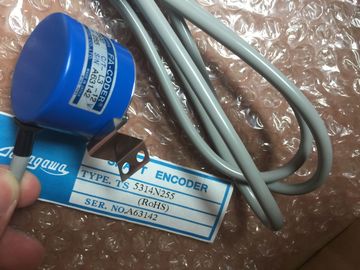
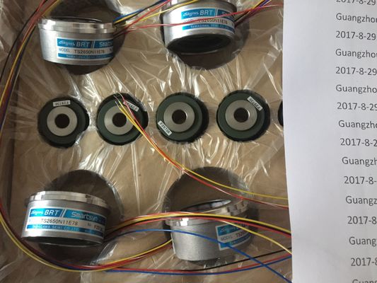
| Brand Name: | Tamagawa |
| Certification: | CE |
| Model Number: | TS5016N60 |
| Minimum Order Quantity: | 1pcs |
|---|---|
| Packaging Details: | carton |
| Delivery Time: | in stock |
| Payment Terms: | T/T, Western Union, MoneyGram |
| Supply Ability: | 100pcs/week |
| TAMAGAWA: | TAMAGAWA | COLOR: | BLACK |
|---|---|---|---|
| Material: | Iron | Japan: | Japan |
| Temperature: | 30-80 | Wire: | Wire |
| Dimension: | 70mm | TS5016N60: | TS5016N60 |
![]()
![]()
![]()
![]()
| ded modules and the grounds of the load current power supplies connected to the reference points? |
Table 6-2 Setting the Battery Monitoring Switch If You ... ...Then |
| Mounting and Wiring Modules Are all modules correctly inserted and screwed on? |
Are any necessary cable ducts or fan subassemblies fitted correctly? |
| Are all front connectors correctly wired, plugged into the right modules, and screwed on |
According to the backup concept, Table 6-2 shows how you must set the battery monitoring switch on the different power supply modules. |
TS3103N156
TS5016N60
TS3103N40
TS3641N1E1
TS3641N2E3
TS3641N11E1
TS3641N12E3
TS3664N1E1
TS3664N1E2
TS3664N2E3
TS3664N2E4
TS3664N11E1
TS3664N11E2
TS3664N12E3
TS3664N12E4
TS3667N1E1
TS3667N1E2
TS3667N2E4
TS3667N1E3
TS3667N2E5
TS3667N2E6
TS3667N3E7
TS3667N3E8
do not use battery monitoring, set the BATT INDIC switch to OFF.
use battery monitoring with a single-width
power supply module,
set the BATT INDIC switch to BATT.
want to monitor a backup battery with a
double or triple-width power supply module,
set the BATT INDIC switch to 1BATT.
want to monitor two backup batteries with a
double or triple-width power supply module,
set the BATT INDIC switch to 2BATT.
6.3 Connecting a Programming Device (PG) to an
Connecting a Programming Device (PG) to an
You must connect the programming device via a connecting cable to the MPI of the
CPU. This allows access via the communication bus to all CPUs and
programmable modules.The following conditions apply when communicating between a programming
device and a CPU:
• You need a programming device with STEP 7.
• The CPU can communicate with the programming device in the following
modes: RUN, STOP, STARTUP, and HOLD.
Operator Control
A description of operator control of communication between CPUs and
programming devices can be found in the STEP 7 manuals.
6.4 Switching On an for the First Time
Switching On an for the First Time
First switch on the power cutout.
Then set the standby switch of the power supply module from the standby setting
to the I setting (output voltages at rated value).
Result:
• On the power supply module, the green 5 VDC and 24 VDC LEDs light up.
• On the CPU
-- The yellow CRST LED lights up;
-- The yellow STOP LED flashes for three seconds at 2 Hz. During this time the
CPU automatically executes a reset.
-- The yellow STOP LED lights up after the automatic reset.
If the red BAF LED and one of the yellow LEDs (BATTF or BATT1F or BATT2F)
light up on the power supply module, check the backup battery/batteries, the
setting of the BATT INDIC switch, or read the section on controls and indicators of
the power supply modules in Chapter 3 of the Reference Manual, Module
Specifications.When you reset a CPU, you place the memories of the CPU in a defined initial
state. The CPU also initializes its hardware parameters and some of the system
program parameters. If you have inserted a Flash card with a user program in the
CPU, the CPU transfers the user program and the system parameters stored on
the Flash card into the main memory after the memory reset.
When Should a CPU be Reset?
You must reset the CPU:
Before transferring a new, complete user program to the CPU.
• When the CPU requests a reset. Your recognize this request by slow flashing of
the STOP LED at 0.5 Hz.
How to Perform a Memory Reset
There are two ways of resetting the CPU:
• Reset with the mode selector switch
• Reset from the programming device (see STEP 7)
Resetting the CPU with the mode selector is described in the following sectionFigure 6-2 Positions of the mode selector switch
Proceed as follows to reset the CPU using the mode switch:
Case A: You want to transfer a new, complete user program to the CPU.
1. Set the switch to STOP setting.
Result: The STOP LED lights up.
2. Set the switch to MRES and hold it there.
Result: The STOP LED is switched off for one second, on for one second, off
for one second and then remains on.
3. Turn the switch back to the STOP setting, then to the MRES setting again within
the next 3 seconds, and back to STOP.
Result: The STOP LED flashes for at least 3 seconds at 2 Hz (reset is being
executed) and then remains lit.
Case B: The CPU requests a reset by slow flashing of the STOP LED at 0.5 Hz
(system reset request, for example, when a memory card has been removed or
inserted).
Set the switch to MRES and then back to STOP.
Result: The STOP LED flashes for at least 3 seconds at 2 Hz (reset is being
executed) and then remains lit.When you carry out a memory reset, the following process occurs in the CPU:
• The CPU deletes the entire user program from the main memory and load
memory (integrated RAM and, if applicable, RAM card).
• The CPU clears all counters, bit memory, and timers (except for the time of
day).
• The CPU tests its hardware.
TS3667N11E1