|
| Place of Origin: | Japan |
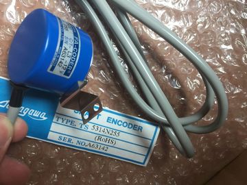
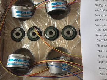
| Brand Name: | Tamagawa |
| Certification: | CE |
| Model Number: | TS5016N61 |
| Minimum Order Quantity: | 1pcs |
|---|---|
| Packaging Details: | carton |
| Delivery Time: | in stock |
| Payment Terms: | T/T, Western Union, MoneyGram |
| Supply Ability: | 100pcs/week |
| TAMAGAWA: | TAMAGAWA | Temperature: | 20-80 |
|---|---|---|---|
| Color: | Black | Material: | Iron |
| TS5016N61: | TS5016N61 | Wire: | Wire |
| Japan: | Japan |
![]()
![]()
![]()
![]()
| he table below lists the smoothing settings of the electrically isolated analog input module SM 331; |
|
| AI 8 x 16 Bit. Enter these codes according to the required smoothing at the relevant | |
| byte of data record 128 (see previous figure.) |
TS3103N156
TS5016N61
TS4244N10E24
TS1982N56E18
800123-R-F
TS3653N65E27
TS5208N23
TS3630N101E2
TS5017N56
TS5005N122
TS4244N3E24
TS1983N146E5
TS3653N81E27
TS2025N471E69
TS3630N102E4
TS5017N60
TS5007N122
TS4502N1000E200
TS1983N146E5
The table below shows all parameters you can set at analog input module
SM 331; AI 6 x TC.
The comparison illustrates the parameters you can edit:
● In STEP 7
● Using SFC55 "WR_PARM"
Parameters set in STEP 7 can also be transferred to the module using SFC56 and SFC57
(refer to the STEP 7 manuals).
To enable diagnostic interrupts in the user program at data record 1, you first need to enable
diagnostics at data record 0 in STEP 7.
The figure below shows the structure of data record 1 for the parameters of analog input
module SM 331; AI 6 x TC. You enable a parameter by setting a logical "1" at the
corresponding bit.
The table below lists all smoothing codes to be entered at the corresponding byte of data
record 1.
nce junction
The table below lists the codes for the external reference junction, to be entered at the
corresponding byte of data record 1.
The table below lists the codes for the temperature coefficient, to be entered at the
corresponding byte of data record 1.
When selecting a temperature coefficient by writing data record 1 via an SFC or a GSD file,
the same temperature coefficient must be specified for every channel which uses the
external reference junction. If you select different temperature coefficients, this will lead to a
parameter fault.
The table below lists all parameters you can set for analog output modules. The comparison
shows:
● which parameters you can edit in STEP 7, and
● which parameters you can change using SFC55 "WR_PARM".
Parameters set in STEP 7 can also be transferred to the module using SFC56 and SFC57.
Table A- 30 Parameters of analog output modules
Diagnostics: Group diagnostics 0 No Yes
Diagnostic interrupt enable 1 Yes Yes
Reaction to CPU STOP Yes Yes
Output type Yes Yes
Output range Yes Yes
Substitute value
To enable diagnostic interrupts in the user program at data record 1, you first need to enable
diagnostics at data record 0 in STEP 7.
The figure below shows the structure of data record 1 for the parameters of analog output
modules.
You enable diagnostic interrupts by setting a logic "1" at the corresponding bit of byte 0.
The table below lists all output types/ranges of the analog output modules, including their
codes. Enter these codes at bytes 2 to 5 in data record 1 (refer to the previous figure.)
Diagnostics: Group diagnostics 0 no yes
Diagnostics interrupt enable 1 yes yes
Reaction to CPU STOP yes yes
Output type yes yes
Output range
TS3653N78E5