 |
| Place of Origin: | Japan |
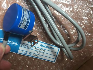
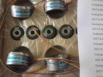
| Brand Name: | Tamagawa |
| Certification: | CE |
| Model Number: | TS5213N551 |
| Minimum Order Quantity: | 1pcs |
|---|---|
| Packaging Details: | carton |
| Delivery Time: | in stock |
| Payment Terms: | T/T, Western Union, MoneyGram |
| Supply Ability: | 100pcs/week |
| TAMAGAWA: | TAMAGAWA | Temperature: | 20-80 |
|---|---|---|---|
| Material: | Iron | Color: | Black |
| TS5213N551: | TS5213N551 | Japan: | Japan |
| To enable diagnostics interrupts in the user program at data record 1, you first need to enable diagnostics at data record 0 in STEP 7. | |
| The figure below shows the structure of data record 1 for the parameters of SM 332; AO 8 x | |
| 12 Bit. You enable diagnostics interrupts by setting a logic "1" at the corresponding bit of byte 0 |
TS3103N156
TS5213N551
TS3653N94E5
TS5208N141E78
TS3630N22E4
TS5146N10
TS5208N500
TS4502N2000E100
TS3503N11E43
TS3653N181E8
TS3684N1E3
TS3631N1E1
TS5146N11
TS5208N510
TS4503N1000E200
TS3062E3
TS3658N3
TS3684N13E8
TS3636N6
TS-5170-N20
The table lists the output types/ranges of SM 332; AO 8 x 12 Bit, including their codes. Enter
these codes at bytes 2 to 9 in data record 1 (refer to the previous figure.)
The table below lists all parameters you can set for analog IO modules.
The comparison illustrates the parameters you can edit:
● in STEP 7
● using SFC 55 "WR_PARM"
Parameters set in STEP 7 can also be transferred to the module using SFC 56 and SFC 57
(refer to the STEP 7 manuals)
The figure below shows the structure of data record 1 for the parameters of analog IO
modules.
You enable a parameter by setting a logic "1" at the corresponding bit of byte 0.
ods and ranges
The table below lists all measuring methods/ranges of analog IO modules, including their
codes. Enter these codes at bytes 2 to 5 in data record 1 (refer to the previous figure.)
disabled 2#0000 disabled 2#0000
Voltage 2#0001 0 V to 10 V 2#1000
Resistance (4-wire connection) 2#0100 10 kΩ 2#1001
Thermal resistance + linearization 4-wire connection
The table below lists all output types/ranges of analog IO modules, including their codes.
Enter these codes at bytes 6 and 7 of data record 1 (refer to the previous figure.)
Table A- 36 Output range codes of analog IO modules
This appendix describes the diagnostic data structure in system data. You should be
sufficiently familiar with this structure if you want to evaluate the diagnostics data of the
signal module in the STEP 7 user program.
Diagnostics data are saved to data records
The diagnostics data for a module is stored in data records 0 and 1.
● Data record 0 contains 4 bytes of diagnostics data describing the current state of the
module.
● Data record 1 contains the 4 bytes of diagnostics data also stored in data record 0, plus
additional module-specific diagnostics data, which describes the status of a channel or a
channel group.
Further references
For detailed information on the evaluation of the diagnostics data of signal modules in the
user program and on corresponding SFCs, refer to the STEP 7 manuals
The section below describes the structure and content of the various bytes in diagnostics
data. General rule: A fault is indicated by a logic "1" at the relevant bit.
Bytes 4 to 6 form the info block, which contains information relating to the channel type, the
length of the diagnostic information, and the number of channels.
Bytes 4 to 6 form the info block, which contains information relating to the channel type, the
length of the diagnostic information, and the number of channels.
The channel fault vector is at least 1 byte long. For modules with more than 8 channels, the
channel fault vector occupies several bytes.
The channel-specific diagnostics data comes after the channel fault vector; refer to section
Channel-specific diagnostics data (Page 588).
If another channel type is available (see Figure "Bytes 4 to 6 of diagnostics data"), the
channel type with the same structure as that described above (channel type, length of
diagnostics data, number of channels of the same type, channel fault vector, channelspecific
diagnostics data of the channel type) follows after the channel-specific diagnostics
data.
The channel-specific diagnostic data follow the channel error vector. The number of bytes
used per channel for channel-specific diagnostics depends on the number of bits entered in
byte 5 "Length of the diagnostic information".
The following figures show the assignment of the diagnostic byte for a channel or a channel
group of the special module. The following generally applies: When an error occurs, the
corresponding bit is set to "1".
A description of possible causes of the fault and corresponding corrective measures can be