 |
| Place of Origin: | Japan |
| Brand Name: | Tamagawa |
| Certification: | CE |
| Model Number: | TS5017N60 |
| Minimum Order Quantity: | 1pcs |
|---|---|
| Packaging Details: | carton |
| Delivery Time: | in stock |
| Payment Terms: | T/T, Western Union, MoneyGram |
| Supply Ability: | 100pcs/week |
| TAMAGAWA: | TAMAGAWA | TS5017N60: | TS5017N60 |
|---|---|---|---|
| Japan: | Japan | Material: | Iron |
| Temperature: | 40-120 | Color: | Black |
| Dimension: | 50mm |
TS3103N156
TS5017N60
TS2651N111E78
TS2014N181E32
TS5013N60,
TS5013N61,
TS5016N60,
TS5017N60,
TS5013N68,
TS5
013N69
TS5013N60
TS5016N60
TS5013N60
TS5016N60
TS5017N60
TS5013N68
TS5013N69
TS2014N181E32
TS2014N311E32
TS2650N11E78
TS2650N1E78
TS5081N1
TS5084N250
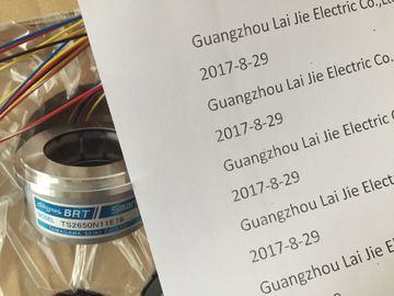
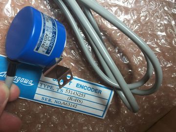
TS5314N255
TS5303N510
TS5622N131
TS1616N200
TS1501N13
TS5641N154
TS5205N454
TS5668N20
TS5667N120
TS5667N420
TS5308N616
TS3462N1E76
TS5214N561
TS5214N510
TS2014N182E32
TS3653N2E5
TS5320N510
TS5016N60
TS5016N60
TS2651N111E78
TS2014N181E32
TS5208N130
![]()
![]()
![]()
![]()
| interrupt and calls OB 82. | |
| If you have set "Enable Diagnostic Interrupt" in STEP 7, the system triggers a diagnostic | |
| The SF LED on the module is lit. |
Reading diagnostic messages
You can read detailed diagnostic messages using SFCs in the user program (refer to section
Diagnostics data of SM 338; POS-INPUT (Page 596)).
You can view the cause of the error in the module diagnostics data in STEP 7 (refer to the
STEP 7 Online Help.)
Diagnostic message using the SF LED
The SM 338 indicates errors at its SF LED (group error LED.) The
SF LED lights up when the SM 338 generates a diagnostic message. It goes dark after all
error states are cleared.
The SF LED also lights up to indicate external errors (short-circuit at the encoder supply),
regardless of the CPU operating state (at POWER ON.)
The SF LED lights up temporarily at startup, during the self test of SM 338.
The table below provides an overview of the diagnostic messages of SM 338; POS-INPUT.
Table 7- 5 Diagnostic messages of SM 338; POS INPUT
Module error Any, the module has detected an error.
Internal error Module has detected an error within the
automation system.
External error Module has detected an error outside of the
automation system.
Channel error Indicates that only specific channels are
faulty.
External auxiliary voltage
missing
Supply voltage L+ of the module is missing Feed supply L+
Module not programmed Module requires information whether it
should operate with default system parameters
or user parameters.
Message present after power on, until the
CPU has completed the transfer of parameters;
configure the module as required.
Incorrect parameters One parameter, or the combination of parameters,
is not plausible
Program the module
Channel information available
Channel error; module can provide additional
channel information.
Watchdog time-out Infrequent high electromagnetic interference Eliminate interference
Channel error Any, the module has detected an error at the
encoder input.
Configuration / programming
error
Illegal parameter transferred to module Program the module
External channel error
(encoder error)
Wire-break at encoder cable, encoder cable
not connected, or encoder defective.
Check connected encoder
This chapter describes the interrupt reaction of SM 338; POS-INPUT. The SM 338 can
trigger diagnostic interrupts.
For detailed information on the OBs and SFCs mentioned below, refer to the STEP 7 Online
Help.
Enabling interrupts
There is no default interrupt setting, i.e. interrupts are disabled if not set accordingly. You
configure the interrupt enable parameter in STEP 7 (refer to chapter "Parametrization
SM 338 POS-INPUT (Page 505)").
Diagnostic interrupt
If you have enabled diagnostic interrupts, the incoming error events (initial occurrence of the
error) and outgoing error events (message after troubleshooting) are reported by means of
interrupts.
The CPU interrupts user program execution, and executes diagnostic interrupt OB82.
You can call SFC 51 or 59 in OB82 in the user program to view detailed diagnostic data
output by the module.
Diagnostics data remain consistent until the program exits OB 82. The module
acknowledges the diagnostic interrupt when the program exits OB82
Dimensions W x H x D (mm) 40 x 125 x 120
Weight Approx. 235 g
Voltages, currents, electrical potentials
Rated load voltage L+
• Range
• Reverse polarity protection
24 VDC
20.4 ... 28.8 V
No
Electrical isolation No, only to shield
Maximum potential difference
• Between the input (M terminal) and CPU grounding busbar
1 VDC