 |
| Place of Origin: | Japan |
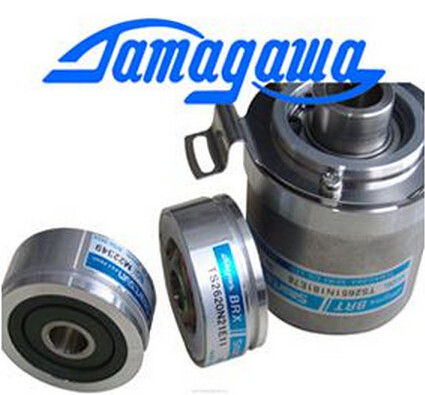
| Brand Name: | Tamagawa |
| Certification: | CE |
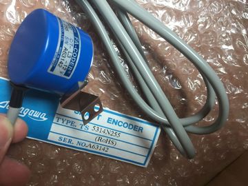
| Model Number: | TS5312N250 |
| Minimum Order Quantity: | 1pcs |
|---|---|
| Packaging Details: | carton |
| Delivery Time: | in stock |
| Payment Terms: | T/T, Western Union, MoneyGram |
| Supply Ability: | 100pcs/week |
| TAMAGAWA: | TAMAGAWA | Material: | Iron |
|---|---|---|---|
| Color: | Black | Temperature: | 30-80 |
| TS5312N250: | TS5312N250 | Wire: | Wire |
| Japan: | Japan |
TS3103N156
TS5312-N250
TS3653N3E8
TS3684N1E3
TS3684N2E6
TS3684N3E8
TS3667N3E8
TS3624N2E3
TS3624N2E4
TS3624N3E6
TS3630N1E1
TS3630N2E3
TS3630N1306
TS3630N1303E9
TS3630N1214E3
TS5013N60
TS5013N61
TS5016N60
TS5013N63
TS5013N64
TS5016N61
TS5013N66
TS5016N63
![]()
![]()
![]()
![]()
| In non-isochronous mode, the encoder values are acquired cyclically. | |
| In isochronous mode, the encoder values are acquired in synchronism with the PROFIBUS DP cycle at each Ti. |
|
| Cyclic encoder value acquisition |
The SM 338 always initiates a frame transfer at the end of the programmed monoflop time.
Asynchronously to these cyclic frames, the SM 338 processes the acquired encoder values
cyclically, based on its refresh rate (refer to the chapter "Technical data of SM 338; POSINPUT
(Page 512)").
Thus, cyclic acquisition returns encoder values of different ages. The difference between the
min./max. age represents the jitter (refer to the chapter "Technical data of SM 338; POSINPUT
(Page 512)".)
Isochronous encoder value acquisition
Isochronous encoder values acquisition is automatically set when the DP master system
operates with active constant bus cycle, and the DP slave is in synchronism with the DP
cycle.
SM 338 initiates a frame transfer in each
PROFIBUS DP cycle, at the time Ti.
The SM 338 processes the transferred encoder values in synchronism with the PROFIBUS
DP cycle.
7.4.3.2 Gray code/binary code converter
When Gray code is set, the Gray code value returned by the absolute value encoder is
converted into binary code. When binary code is set, the values returned by the encoder
remain unchanged.
Note
When you set Gray code, the SM 338 always converts the entire encoder value (13, 21, 25
bits). As a result, any leading special bits will influence the encoder value, and the appended
bits may be corrupted.
The transferred encoder value contains the encoder position of the absolute value encoder.
In addition to the encoder position, the encoder transfers additional bits located before and
after the encoder position, depending on the encoder used.
The SM 338 determines the encoder position based on the following settings:
● Scaling, places (0..12), or
● scaling, steps / revolution
Scaling determines the position of the encoder value at the feedback interface.
● "Places" = 1, 2....12 indicates that appended irrelevant bits in the encoder value are
shifted out, and the encoder value is right-aligned in the address area (see the example
below.)
● "Places" = 0 determines that appended bits are retained and available for evaluation.
This may be useful when the absolute value encoder used transfers information in the
appended bits (see manufacturer specifications) which you want to evaluate. Refer also
to chapter "Gray code/binary code converter (Page 502)".
Steps per revolution parameter
Up to 13 bits are available for the steps per revolution parameter. The resultant number of
steps per revolution is displayed automatically according to the "Places" setting.
Example of encoder value scaling
You are using a single-turn encoder with
29 steps = 512 steps per revolution (resolution/360°.)
Your configuration in STEP 7: