 |
| Place of Origin: | Japan |
| Brand Name: | Tamagawa |
| Certification: | CE |
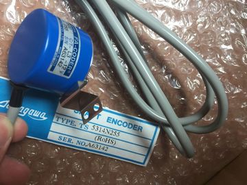
| Model Number: | TS5313N122 |
| Minimum Order Quantity: | 1pcs |
|---|---|
| Packaging Details: | carton |
| Delivery Time: | in stock |
| Payment Terms: | T/T, Western Union, MoneyGram |
| Supply Ability: | 100pcs/week |
| TAMAGAWA: | TAMAGAWA | Temperature: | 30-120 |
|---|---|---|---|
| TS5313N122: | TS5313N122 | Color: | Black |
| Material: | Iron | Wire: | Wire |
| Japan: | Japan |
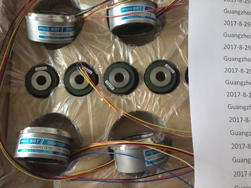
TS5313N122
TS252N30E1
TS3503N11E43
TS3062E3
TS3092N11E12
TS3095N2
TS3103N156
TS3103N178
TS3103N255
TS3103N302
TS3103N40
TS3132N32
TS3134N21
TS3134N22
TS3134N317
TS3134N52
TS3166
TS3166N43
TS3212N32
TS3214N12
TS3214N13
TS3214N15
TS3214N16
TS3214N44
![]()
![]()
![]()
![]()
| minimum interval between two SSI frames. |
|
| The configured monoflop time must be greater | |
| than the monoflop time of the absolute value |
encoder.
Scaling
? Places
? Steps per revolution 4
0 to 12
2 to 8192
Scaling right-aligns the encoder value in the address
space; irrelevant places are discarded.
Enabling the Freeze function off; 0; 1 Definition of the digital input that initiates freezing
of the encoder value at the positive edge.
1 Refer to the technical specifications of the absolute value encoder
2 The monoflop time represents the interval between two SSI frames. The configured monoflop
time must be greater than the monoflop time of the absolute value encoder (see the
technical data of the manufacturer). The time 2 x (1 / transmission rate) is added to the
value set in HW Config. A transmission rate of 125 kHz and configured monoflop time of
16 μs sets an effective monoflop time of 32 μs.
3 Restriction of the monoflop time of the absolute value encoder:
(1 / transmission rate) < monoflop time of the absolute value encoder < 64 μs + 2 x (1 /
transmission rate)
4 to powers of two
Please note that in asynchronous mode, the transmission rate and monoflop time affect the
accuracy and update quality of the encoder values. In isochronous mode, the transmission
rate and monoflop time have an influence on the accuracy of the freeze function.
The SM 338 inputs and outputs are addressed beginning at the module start address. The
input and output address is determined in your configuration of SM 338 in STEP 7.
In the double data word from channel 0, the status of digital input I0 is reported to bit 27
(digital input status) and the double data word from channel 1 is reported to digital input I1.
In the double data word from channel 2, the bit is always = 0.
You can read the data areas in your user program using the STEP 7 operation L PED "xyz."
Example of access to encoder values and use of the freeze function
You want to read and evaluate the values at the encoder inputs. The module start address is
256.
You can then process the encoder values from the bit memory address areas MD 100, MD
104 and MD 108. The encoder value is set in bits 0 to 30 of the memory double word.
The SM 338 provides diagnostics messages, i.e. it always provides all diagnostics messages
without user intervention.
Reactions to a diagnostic message in STEP 7
Actions initiated by diagnostic messages:
● The diagnostic message is entered in the diagnosis of the module and forwarded to the
CPU.
● The SF LED on the module is lit.
● If you have set "Enable Diagnostic Interrupt" in STEP 7, the system triggers a diagnostic
interrupt and calls OB 82.
Reading