|
| Place of Origin: | Japan |
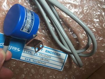
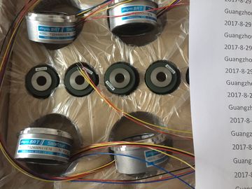
| Brand Name: | Tamagawa |
| Certification: | CE |
| Model Number: | TS5208N131 |
| Minimum Order Quantity: | 1pcs |
|---|---|
| Packaging Details: | carton |
| Delivery Time: | in stock |
| Payment Terms: | T/T, Western Union, MoneyGram |
| Supply Ability: | 100pcs/week |
| TAMAGAWA: | TAMAGAWA | Material: | Iron |
|---|---|---|---|
| TS5208N131: | TS5208N131 | Japan: | Japan |
| Color: | Black | Temperature: | 20-80 |
| Wire: | Wire |
TS3103N156
TS5208N131
TS3684N2E6
TS3684N3E8
TS3684N11E3
TS3684N12E6
TS3684N13E8
TS3617N1E3
TS3617N1E1
TS3617N1E2
TS3617N2E4
TS3617N2E5
TS3617N2E6
TS3617N2E7
TS3617N3E8
TS3617N3E9
TS3617N3E1
TS3617N11E3
TS3617N11E1
TS3617N11E2
TS3617N12E4
![]()
![]()
![]()
| Voltages, currents, electrical potentials | |
| Rated load voltage L+ Range | |
| Reverse polarity protection |
24 VDC
20.4 ... 28.8 V
No
Electrical isolation No, only to shield
Maximum potential difference
? Between the input (M terminal) and CPU grounding busbar
1 VDC
Encoder supply
? Output voltage
? Output current
L+ -0.8 V
Max. 900 mA, short circuit-proof
Current consumption
? from the backplane bus
? from load voltage L+ (no load)
Max. 160 mA
max. 10 mA
Power loss of the module Typ. 3 W
Encoder inputs POS-INPUT 0 to 2
Position detection Absolute
Difference signals for SSI data and SSI clock To RS422 standard
Data transfer rate and cable (twis
Electrical isolation No, only to shield
Input voltage 0 signal -3 V ... 5 V
1 signal 11 V ... 30.2 V
Input current 0 signal ≤ 2 mA (standby current)
1 signal 9 mA (typ.)
Input delay 0 > 1: max. 300 μs
1 > 0: Max. 300 μs
Maximum repetition rate 1 kHz
Connection of a two-wire BEROS, type 2 Supported
Shielded cable length 600 m
Unshielded cable length 32 m
Status, interrupts, diagnostics
Interrupts
? Diagnostics interrupt programmable
Status display for digital inputs
Group error
LED (green)
LED (red)
Inaccuracy of the encoder value
Free-running transducer capture (Standard Mode)
? maximum age 1
? minimum age 1
? Jitter
(2 × frame transfer rate) + monoflop time + 580 μs
Frame transfer rate + 130 μs
Frame transfer rate + monoflop time + 450 μs
Refresh rate Frame evaluation at intervals of 450 μs
Free-running transducer capture (Fast Mode)
? maximum age 1
? minimum age 1
? Jitter
(2 × frame transfer rate) + monoflop time + 400 μs
Frame transfer rate + 100 μs
Frame transfer rate + monoflop time + 360 μs
Refresh rate Frame evaluation at intervals of 360 μs
Isochronous encoder value acquisition
? Age Encoder value at time Ti of the current PROFIBUS DP cycle
Inaccuracy of the frozen encoder value (Freeze)
Cyclic encoder value acquisition (Standard Mode)
? maximum age 1
? minimum age 1
? Jitter
(2 × frame transfer rate) + monoflop time + 580 μs
Frame transfer rate + 130 μs
Frame transfer rate + monoflop time + 450 μs
Isochronous encoder value acquisition
? Jitter Max. (frame transfer rate n + programmed Monoflop time n)
=0, 1, 2, (channel)
Age of the encoder values determined by the transfer process and the processing
2 Restriction of the monoflop time of the absolute value encoder:
(1 / transmission rate) < monoflop of the absolute value encoder < 64 μs + 2 x (1 / transmission
rate)
This chapter described the technical data and properties of the S7-300 interface modules.
8.1 Module overview
Introduction
The table below summarizes the essential features of the interface modules described in this
chapter. This overview supports you in selecting a module to suit your requirements.
Table 8- 1 Interface modules: Overview of properties
Properties Interface module IM 360 Interface module IM 361 Interface module IM 365
Suitable for installation
in S7-300 racks
? 0 ? 1 to 3 ? 0 and 1
Data transfer ? from IM 360 to
IM 361 via connecting
cable 386
? from IM 360 to
IM 361, or from IM
361 to IM 361, via
connecting cable 386
? from IM 365 to IM 365 via connecting
cable 386
Distance between... ? max. 10 m ? max. 10 m ? 1 m, permanently connected
Special features --- --- ? Preassembled module pair
? Rack 1 supports only signal modules
? IM 365 does not route the communication
bus to rack 1
6ES7360-3AA01-0AA0
Properties
Special features of interface module IM 360:
● Interface for rack 0 of the S7-300
● Data transfer from IM 360 to IM 361 via connecting cable 368
● Maximum distance between IM 360 and IM 361 is 10 m
Status and error LEDs