|
| Place of Origin: | Japan |
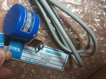
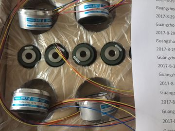
| Brand Name: | Tamagawa |
| Certification: | CE |
| Model Number: | TS5641N150 |
| Minimum Order Quantity: | 1pcs |
|---|---|
| Packaging Details: | carton |
| Delivery Time: | in stock |
| Payment Terms: | T/T, Western Union, MoneyGram |
| Supply Ability: | 100pcs/week |
| TAMAGAWA: | TAMAGAWA | Temperature: | 30-120 |
|---|---|---|---|
| TS5641N150: | TS5641N150 | Color: | Black |
| Material: | Iron | Japan: | Japan |
| Wire: | Wire |
| Interface module IM 360 is equipped with the following status and error LEDs | |
| 6ES7361-3CA01-0AA0 Properties |
|
| Special features of interface module IM 361: |
TS3103N156
TS5641N150
TS3617N13E8
TS3617N13E9
TS3617N13E1
TS3653N1E1
TS3653N1E2
TS3653N1E3
TS3653N2E4
TS3653N2E5
TS3653N2E6
TS3653N3E7
TS3653N3E8
TS3653N3E9
TS3653N11E1
TS3653N11E2
TS3653N11E3
TS3653N12E4
TS3653N12E5
TS3653N12E6
TS3653N13E7
TS3653N13E8
24 VDC power supply
● Interface for racks 1 to 3 of the S7-300
● Current output via the S7-300 backplane bus: max. 0.8 A
● Data transfer from IM 360 to IM 361, or from IM 361 to IM 361 via connecting cable 368
● Maximum distance between IM 360 and IM 361 is 10 m
● Maximum distance between IM 361 and IM 361 is 10 m
Status and error LEDs
Interface module IM 361 is equipped with the following status and error LEDs.
Dimensions and weight
Dimensions W x H x D (mm) 80 x 125 x 120
Weight 505 g
Module-specific data
Cable length
Maximum length to next IM 10 m
Current consumption
from 24 VDC
Power loss
0.5 A
typ. 5 W
Current sinking at backplane bus 0.8 A
Status and error LEDs yes
6ES7365-0BA01-0AA0
Order number: "SIPLUS S7-300 module"
6AG1365-0BA01-2AA0
Properties
Special features of interface module IM 365:
● Preassembled pair of modules for rack 0 and rack 1
● Total power supply of 1.2 A, of which up to 0.8 A may be used per rack.
● Connecting cable with a length of 1 m already permanently connected
● IM 365 does not route the communication bus to rack 1, i.e. you cannot install FMs with
communication bus function in rack 1.
Dimensions W x H x D (mm) per module 40 x 125 x 120
Total weight 580 g
Module-specific data
Cable length
Maximum length to next IM 1 m
Current consumption
from the backplane bus
Power loss
100 mA
typ. 0.5 W
Current sinking
per module
max. 1.2 A
0.8 A
Status and error LEDs no
You have programmed the modules in STEP 7.
In the user program, you can use a SFC:
● to assign new parameters to the module, and
● transfer the parameters from the CPU to the addressed signal module
Parameters are stored in data records
The signal module parameters are written to data records 0 and 1; for certain analog input
modules, these are also written to data record 128
You can edit the parameters of data record 1, and then transfer these to the signal module
using SFC55. The CPU parameters are not changed by this action!
You cannot modify any parameters of data record 0 in the user program.
SFCs for programming
SFCs available for programming signal modules in the user program:
Table A- 1 SFCs for programming signal modules
SFC no. Identifier Application
55 WR_PARM Transfer the programmable parameters (data record 1 and 28) to the addressed
signal module.
56 WR_DPARM Transfer the parameters (data record 0, 1 or 128) from the CPU to the addressed
signal module.
57 PARM_MOD Transfer all parameters (data record 0, 1 and 128) from the CPU to the addressed
signal module.
The next chapters describe all modifiable parameters of the various module classes. For
information on signal module parameters, refer to:
● the STEP 7 Online Help