|
| Place of Origin: | Japan |
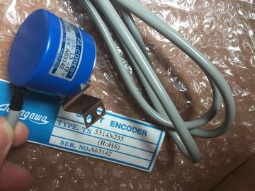
| Brand Name: | Tamagawa |
| Certification: | CE |
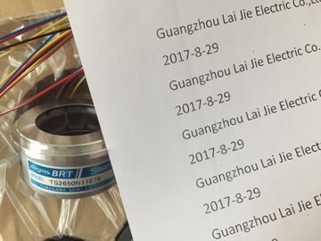
| Model Number: | TS2640N321E64 |
| Minimum Order Quantity: | 1pcs |
|---|---|
| Packaging Details: | carton |
| Delivery Time: | in stock |
| Payment Terms: | T/T, Western Union, MoneyGram |
| Supply Ability: | 100pcs/week |
| Tamagawa: | Tamagawa | TS2640N321E64: | TS2640N321E64 |
|---|---|---|---|
| Temperature: | 30-80 | Material: | Iron |
| Color: | Black | Japan: | Japan |
| Wire: | Wire |
| to this Reference Manual The chapters dealing with the various signal modules also show you the corresponding configurable parameters. |
|
| Further references For detailed information on programming signal modules in the user program and on corresponding SFCs, refer to the STEP 7 manuals. |
|
| The table below lists the parameters you can set for digital input modules. Note |
TS3103N156
TS2640N321E64
TS3653N12E4
TS3653N12E5
TS3653N12E6
TS3653N13E7
TS3653N13E8
TS3653N13E9
TS3103N40
TS3641N1E1
TS3641N2E3
TS3641N11E1
TS3641N12E3
TS3664N1E1
TS3664N1E2
TS3664N2E3
TS3664N2E4
TS3664N11E1
TS3664N11E2
For details on parameters of programmable digital IO modules, see the chapter dealing with
the relevant module.
The comparison illustrates the parameters you can edit:
● in STEP 7
● using SFC55 "WR_PARM"
● using SFB53 "WRREC" (for GSD, for example).
Parameters set in STEP 7 may also be transferred to the module using SFCs 56 and 57, and
SFB53 (refer to the STEP 7) Online Help
The table below contains all parameters you can set for digital output modules.
Note
For details on the parameters of programmable digital IO modules, see the chapter dealing
with the relevant module.
The comparison illustrates the parameters you can edit:
● in STEP 7
● using SFC55 "WR_PARM"
● using SFB53 "WRREC" (for GSD, for example).
Parameters set in STEP 7 may also be transferred to the module using SFCs 56 and 57, and
SFB 53 (refer to the STEP 7) Online Help).
To enable diagnostic interrupts in the user program at data record 1, you first need to enable
diagnostics at data record 0 in STEP 7.
The figure below shows the structure of data record 1 for the parameters of digital output
modules.
You enable a parameter by setting a logic "1" at the corresponding bit of byte 0.
The table below contains all parameters you can set for digital output modules.
The comparison illustrates the parameters you can edit:
● inSTEP 7
● using SFC55 "WR_PARM"
● using SFB53 "WRREC" (for GSD, for example).
Parameters set in STEP 7 can also be transferred to the module using SFC 56 and SFC 57
(refer to the STEP 7 Online Help).
Table A- 5 Digital output module SM 322; 6ES7322-8HB10-0AB0
Diagnostics: Group diagnostics 1 Yes Yes
Diagnostics: Load voltage L+ missing
Diagnostics: Discrepancy error
Diagnostics interrupt enable
Behavior at CPU/master STOP
Substitute a value
The figure below shows the structure of data record 1 for the parameters of digital output
modules.
You enable a parameter by setting a logic "1" at the corresponding bit of byte 0
The table below lists all parameters you can set for analog input modules.
The comparison illustrates the parameters you can edit:
● in STEP 7
● using SFC55 "WR_PARM"
Parameters set in STEP 7 can also be transferred to the module using SFC56 and SFC57
(refer to the STEP 7 manuals).