 |
| Place of Origin: | Japan |
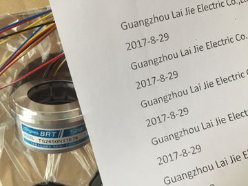
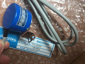
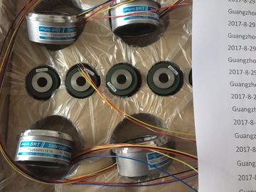
| Brand Name: | Tamagawa |
| Certification: | CE |
| Model Number: | TS5208N111E78 |
| Minimum Order Quantity: | 1pcs |
|---|---|
| Packaging Details: | carton |
| Delivery Time: | in stock |
| Payment Terms: | T/T, Western Union, MoneyGram |
| Supply Ability: | 100pcs/week |
| TAMAGAWA: | TAMAGAWA | Material: | Iron |
|---|---|---|---|
| Temperature: | 30-80 | Color: | Black |
| Japan: | Japan | Wire: | Wire |
| TS5208N111E78: | TS5208N111E78 |
| Table A- 6 Parameters of analog input modules | The figure below shows the structure of data record 1 of the parameters for an analog input |
| To enable diagnostic interrupts in the user program at data record 1, you first need to enable | module with 8 channels in 4 groups (e.g. AI 8 x 12 bits). The structure of a module whose |
| diagnostics at data record 0 in STEP 7. | channels are not grouped together is documented in the relevant module description. |
TS3103N156
TS5208N111E78
TS5205
N450
TS5205
N454
TS5205N452
TS5205
N452
TS5207
TS5208
TS5212
TS5213
TS5214
TS5231
TS5217
TS5233
TS5150
TS5300
TS5100
TS5000
You enable a parameter by setting a logic "1" at the corresponding bit of byte
The representation of limits matches the analog value representation (see chapter 4.)
Observe range limits when setting the limit values.
The table below shows all measurement types and measuring ranges of the analog input
module, including their codes. Enter these codes at bytes 2 to 5 in data record 1 (refer to the
previous figure.)
Note
You may have to reposition a measuring range module of the analog input module to suit the
measuring range.
The table below shows all parameters you can set at analog input module
SM 331; AI 8 x RTD.
The comparison illustrates the parameters you can edit:
● in STEP 7
● using SFC55 "WR_PARM"
Parameters set in STEP 7 can also be transferred to the module using SFC56 and SFC57
(refer to the STEP 7 manuals)
To enable diagnostic interrupts in the user program at data record 1, you first need to enable
diagnostics at data record 0 in STEP 7.
The diagram below shows the structure of data record 1 of SM 331; AI 8 x RTD. You enable
a parameter by setting a logical "1" at the corresponding bit.
The diagram below shows the structure of data record 128 of SM 331; AI 8 x RTD.
The representation of limits matches the analog value representation. Observe range limits
when setting the limit values.
The representation of limits matches the analog value representation. Observe range limits
when setting the limit values.
The table below contains the coding at byte 0 of data record 128 for the various modes of
operation (see the previous figure.)
The table below contains the frequency codes to be entered at byte 1 of data record 128
(see the previous figure.) The 50 Hz, 60 Hz and 400 Hz only apply to 8channel software filter
mode. The 50 Hz, 60 Hz and 400 Hz settings only apply to 4- and 8-channel hardware filter
mode.
The table below shows all measurement types and measuring ranges of the module,
including their codes. Enter these codes at the corresponding bytes of data record 128 (see
the figure Data record 1 for the parameters of analog input modules).
The table below contains the temperature coefficient codes to be entered at the
corresponding byte of data record 128 (refer to the previous figure.)
The table below lists all smoothing codes to be entered at the corresponding byte of data
record 128 (refer to the previous figure.)
The table below shows all parameters you can set at analog input module
SM 331; AI 8 x TC.
The comparison illustrates the parameters you can edit:
● in STEP 7
● using SFC55 "WR_PARM"
Parameters set in STEP 7 can also be transferred to the module using SFC56 and SFC57
(refer to the STEP 7 manuals).
Diagnostics: Group diagnostics 0 no yes
Diagnostics: with wirebreak monitoring no yes
Diagnostic interrupt enable 1 yes yes
Hardware interrupt when limit exceeded yes yes
End of cycle interrupt enable yes yes
Temperature unit yes yes
Measurement type 128 yes yes
Measuring range yes yes
Operating mode yes yes
Response to open thermocouple yes yes
Interference frequency suppression yes yes
Smoothing yes yes
High limit yes yes
Low limit