|
| Place of Origin: | Japan |
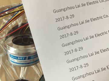
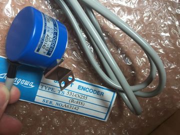
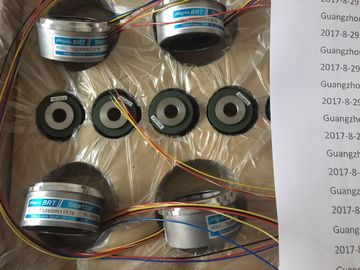
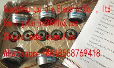
| Brand Name: | Tamagawa |
| Certification: | CE |
| Model Number: | TS2650N11E78 |
| Minimum Order Quantity: | 1pcs |
|---|---|
| Packaging Details: | carton |
| Delivery Time: | in stock |
| Payment Terms: | T/T, Western Union, MoneyGram |
| Supply Ability: | 100pcs/week |
| TAMAGAWA: | TAMAGAWA | Material: | Iron |
|---|---|---|---|
| Color: | Black | Temperature: | 20-80 |
| Japan: | Japan | TS2650N11E78: | TS2650N11E78 |
| Wire: | Wire |
TS3103N156
TS2650N11E78
TS5643
TS2223
TS2224
TS2225
TS20E12
TS13E11
TS5308N616
TS2650N11E78
TS5420N60
TS5208N131
TS3462N1E76
48-2500P8-L6-5VC/T-L3-12V
TS-5016N-60
TS5214N561
TS5214N510
TS2014N182E32
TS3653N2E5
![]()
![]()
![]()
![]()
| To enable diagnostic interrupts in the user program at data record 1, | |
| you first need to enable diagnostics at data record 0 in STEP 7 |
|
| The figure below shows the structure of data record 1 of SM 331; AI 8 x TC |
You enable a
parameter by setting a logical "1" at the corresponding bit.
The table below contains the coding at byte 0 of data record 128 for the various modes of
operation (see the previous figure.)
Table A- 16 Operating mode codes of SM 331; AI 8 x TC
Operating mode Code
The table below contains the frequency codes to be entered at byte 1 of data record 128
(see the previous figure.) The 400 Hz, 60 Hz and 50 Hz settings only apply to 8channel
software filter mode. The 50 Hz, 60 Hz and 400 Hz settings only apply to 4- and 8-channel
hardware filter mode.
ypes and measuring ranges of SM 331; AI 8 x TC
The table below shows all measurement types and measuring ranges of the module,
including their codes. Enter these codes at the corresponding bytes of data record 128 (see
the figure Data record 1 for the parameters of analog input modules).
The table below lists the codes for the reaction to an open thermocouple to enter at the
corresponding byte of data record 128 (refer the previous figure.)
The table below lists all smoothing codes to be entered at the corresponding byte of data
record 128 (refer to the previous figure.)
The figure below shows the structure of data record 1 for the parameters of the analog input
module.
You enable a parameter by setting a logical "1" at the corresponding bit in the bytes.
The table below lists the temperature measurement codes to be enterd at byte 0 of data
record 1 (see the previous figure.)
Table A- 21 Temperature measurement codes of the analog input module
The table below contains the frequency codes to be entered at byte 1 of data record 1 (see
the previous figure.) Make allowances for the resultant integration time at each module!
ypes and measuring ranges
The table below contains all the measurement types and measuring ranges of the analog
input module, including their codes. Enter these codes at bytes 2 to 13 in data record 1 (refer
to the previous figure.)
Note
The front connector of the analog input module must be wired in accordance with the
measuring range!
The table below contains all settings you can set for isolated digital output modules
SM 331; AI 8 ×16 Bit (6ES7331-7NF10-0AB0). This comparison shows which specific
method you can use to configure the various parameters:
● SFC55 "WR_PARM"
● STEP 7 programming device
Parameters set in STEP 7 can also be transferred to the module using SFC56 or SFC57.
Table A- 25 Parameters for the electrically isolated analog input module SM 331; AI 8 x 16 Bit
To enable diagnostic interrupts in the user program at data record 1, you first need to enable
diagnostics at data record 0 in STEP 7.
The figure below shows the structure of data record 1 for the parameters of the electrically
isolated analog input module SM 331; AI 8 x 16 bit.
You enable a parameter by setting a logical "1" at the corresponding bit in byte 0.
The figure below shows the structure of data record 128 for the parameters of the electrically
isolated analog input module SM 331; AI 8 x 16 bit.
The table below lists the frequency codes to be entered at byte 1 of data record 128 (see the
previous figure.) 4-channel mode only works if 50 Hz, 60 Hz and 400 Hz noise suppression
is set.