|
| Place of Origin: | Japan |
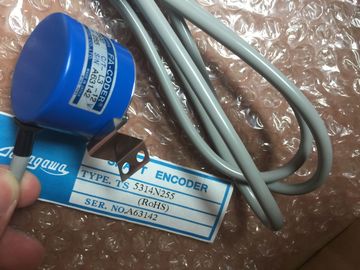
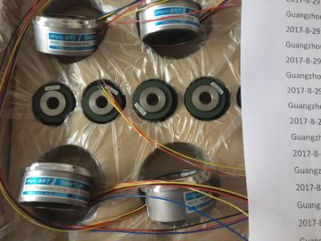
| Brand Name: | Tamagawa |
| Certification: | CE |
| Model Number: | TS2650N11E78 |
| Minimum Order Quantity: | 1pcs |
|---|---|
| Packaging Details: | carton |
| Delivery Time: | in stock |
| Payment Terms: | T/T, Western Union, MoneyGram |
| Supply Ability: | 100pcs/week |
| TAMAGAWA: | TAMAGAWA | TS2650N11E78: | TS2650N11E78 |
|---|---|---|---|
| Japan: | Japan | Color: | Black |
| Material: | Iron | Temperature: | 30-80 |
| Dimension: | 60mm | Wire: | Wire |
| Error condition indicated If EN = TRUE and GetError or GetErrorID executes, then: | You can connect error reaction program logic to ENO which activates after an error occurs. |
| ENO = TRUE indicates a code block execution error occurred and error data is present | an error exists, then the output parameter stores the error data where your program has access to itGetError and GetErrorID can be used to send error information from the currently executing |
| ENO = FALSE indicates no code block execution error occurred | block (called block) to a calling block. Place the instruction in the last network of the called block program to report the final execution status of the called block. |
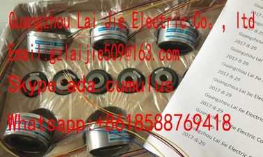
Guang Zhou Lai Jie Electric Co.,LTD
TS5246N160
TS3699N172
TS3699N232
TS3738N1E7
TS3738N1E7
TS3741N3E8
TS374
TS3762N15E4
TS4126N1017E235
TS4127N1017E215
TS4127N1017E235
TS4231N6E17
TS4231N6E17
TS4244N10E24
TS4244N3E24
TS4502N1000E200
TS4502N1202E200
TS4502N2000E100
TS4503N1000E200
the "Create" icon or right-click on an input stub for one of the
existing IN parameters and select the "Insert input" command.
To remove an input, right-click on an input stub for one of the existing IN parameters (when
there are more than the original two inputs) and select the "Delete" command. The corresponding bit values of IN1 and IN2 are combined to produce a binary logic result at
parameter OUT. ENO is always TRUE following the execution of these instructions. Calculates the binary one's complement of the parameter IN. The one's
complement is formed by inverting each bit value of the IN parameter
(changing each 0 to 1 and each 1 to 0). ENO is always TRUE following
the execution of this instruction. SInt, Int, DInt, USInt, UInt, UDInt, Byte, Word, DWord Data element to invert
OUT SInt, Int, DInt, USInt, UInt, UDInt, Byte, Word, DWord Inverted output Encodes a bit pattern to a binary number
The ENCO instruction converts parameter IN to the binary number
corresponding to the bit position of the least-significant set bit of
parameter IN and returns the result to parameter OUT. If
parameter IN is either 0000 0001 or 0000 0000, then a value of 0
is returned to parameter OUT. If the parameter IN value is 0000
0000, then ENO is set to FALSE.
out := DECO(_in_); Decodes a binary number to a bit pattern
The DECO instruction decodes a binary number from parameter
IN, by setting the corresponding bit position in parameter OUT to
a 1 (all other bits are set to 0). ENO is always TRUE following
execution of the DECO instruction.
Note: The default data type for the DECO instruction is DWORD.
In SCL, change the instruction name to DECO_BYTE or
DECO_WORD to decode a byte or word value, and assign to a
byte or word tag or address. For LAD and FBD: Click the "???" and select a data type from the drop-down menu. The DECO parameter OUT data type selection of a Byte, Word, or DWord restricts the
useful range of parameter IN. If the value of parameter IN exceeds the useful range, then a
modulo operation is performed to extract the least significant bits shown below.
DECO parameter IN range:
● 3 bits (values 0-7) IN are used to set 1 bit position in a Byte OUT
● 4-bits (values 0-15) IN are used to set 1 bit position in a Word OUT
● 5 bits (values 0-31) IN are used to set 1 bit position in a DWord OUT
SEL assigns one of two input values to parameter OUT, depending
on the parameter G value. SInt, Int, DInt, USInt, UInt, UDInt, Real, LReal, Byte, Word, DWord,
Time, Char
Inputs
OUT SInt, Int, DInt, USInt, UInt, UDInt, Real, LReal, Byte, Word, DWord,
Time, Char MUX copies one of many input values to parameter OUT, depending
on the parameter K value. If the parameter K value exceeds (INn - 1),
then the parameter ELSE value is copied to parameter OUT. To add an input, click the "Create" icon or right-click on an input stub for one of