 |
| Place of Origin: | Japan |
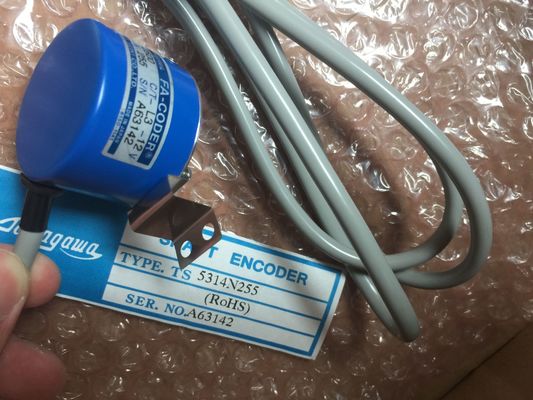
| Brand Name: | Tamagawa |
| Certification: | ce |
| Model Number: | TS2651N141E78 |
| Minimum Order Quantity: | 1pcs |
|---|---|
| Packaging Details: | carton |
| Delivery Time: | in stock |
| Payment Terms: | T/T, Western Union, MoneyGram |
| Supply Ability: | 100pcs/week |
| TAMAGAWA: | TAMAGAWA | TS2651N141E78: | TS2651N141E78 |
|---|---|---|---|
| Japan: | Japan | Material: | Iron |
| Color: | Black | Temperature: | 30-90 |
| Dimension: | 60mm | Wire: | Wire |
| RECORD IN_OUT Variant Target area for the fetched data record (RDREC) | The transfer of the data record is complete when the output parameter BUSY has the value FALSE |
| Data record (WRREC)The RDREC and WRREC instructions operate asynchronously, that is, processing covers | The job status is displayed via output parameter BUSY and the two central bytes of output parameter STATUS. |
| multiple instruction calls. | Start the job by calling RDREC or WRREC with REQ = 1. |
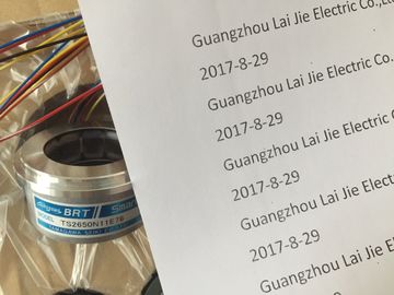
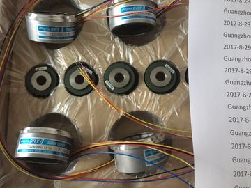
Guang Zhou Lai Jie Electric Co.,LTD
TS2651N141E78
TS3667N3E7
TS3667N3E8
TS3667N11E1
TS3667N11E2
TS3667N12E4
TS3667N11E3
TS3667N12E5
TS3667N12E6
TS3667N31E7
TS3667N13E8
TS3624N1E1
TS3624N1E2
TS3624N2E3
TS3624N2E4
TS3624N3E5
TS3624N3E6
TS3630N1E1
TS3630N1E2
TS3630N2E3
TRUE (only for one scan) on the output parameter VALID (RDREC) or DONE (WRREC)
verifies that the data record has been successfully transferred into the target area RECORD
(RDREC) or to the target device (WRREC). In the case of the RDREC, the output parameter
LEN contains the length of the fetched data in bytes.
The output parameter ERROR (only for one scan when ERROR = TRUE) indicates that a
data record transmission error has occurred. In this case, the output parameter STATUS
(only for the one scan when ERROR = TRUE) contains the error information.
Data records are defined by the hardware device manufacturer. Refer to the hardware
manufacturer's device documentation for details about a data record.
Note
If a DPV1 slave is configured via GSD file (GSD rev. 3 and higher) and the DP interface of
the DP master is set to "S7 compatible", then you may not read any data records from the
I/O modules in the user program with "RDREC" or write to the I/O modules with "WRREC".
In this case, the DP master addresses the wrong slot (configured slot + 3).
Remedy: set the interface of the DP master to "DPV1". The interfaces of the "RDREC" and "WRREC" instructions are identical to the "RDREC" and
"WRREC" FBs defined in "PROFIBUS Guideline PROFIBUS Communication and Proxy
Function Blocks according to IEC 61131-3".
Note
If you use "RDREC" or "WRREC" to read or write a data record for PROFINET IO, then
negative values in the INDEX, MLEN, and LEN parameters will be interpreted as an
unsigned 16-bit integer. Use the RALRM (read alarm) instruction to read diagnostic
interrupt information from PROFIBUS or PROFINET I/O
modules/devices.
The information in the output parameters contains the start
information of the called OB as well as information of the
interrupt source.
Call RALRM in an interrupt OB to return information regarding
the event(s) that caused the interrupt. In the S7-1200, only
diagnostic interrupts (OB82) are supported.
Operating mode
F_ID IN HW_IO (Word) Logical start address of the component (module) from which interrupts
are to be received
Note: The device ID can be determined in one of two ways:
By making the following "Network view" selections:
– Device (gray box)
– "Properties" of the device
– "Hardware identifier"
Note: Not all devices display their Hardware identifiers.
By making the following "Project tree" menu selections: