 |
| Place of Origin: | Japan |
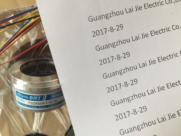
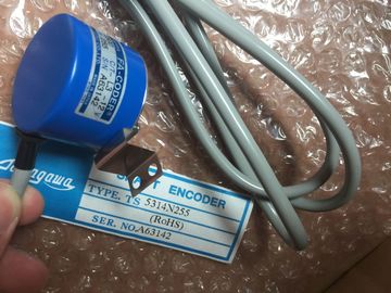
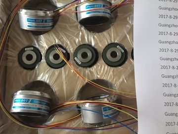
| Brand Name: | Tamagawa |
| Certification: | CE |
| Model Number: | TS5246N430 |
| Minimum Order Quantity: | 1pcs |
|---|---|
| Packaging Details: | carton |
| Delivery Time: | in stock |
| Payment Terms: | T/T, Western Union, MoneyGram |
| Supply Ability: | 100pcs/week |
| TAMAGAWA: | TAMAGAWA | TS5246N430: | TS5246N430 |
|---|---|---|---|
| Japan: | Japan | COLOR: | BLACK |
| Material: | Iron | Temperature: | 20-80 |
| Wire: | Wire | Dimension: | 40mm |
![]()
![]()
![]()
![]()
| Ungrounded configuration | |
| to the reference point of the rack; metallic connection | |
| between frame element and chassis ground must be |
TS3103N156
TS5246N430
TS3617N2E6
TS5214N566
TS5205N450
TS5213N551
TS5208N122
TS5208N23
TS5778N171
TS5210N53
TS5320N510
TS5000N632
TS5212N510
TS5213N510
TS5312N616
TS208N101
TS5208N130
TS5213N530
TS5013N68
TS5214N566
TS5200N500
TS5305N616
TS5669N220
TS5214N564
TS5246N158
TS5667N650
TS5213N551
TS5668N20
TS5667N120
TS5667N420
TS5246N160
TS5312N512
TS5208N122
TS5641N151
TS5270N15
TS5308N616
TS5213N510
TS2014N181E32
TS5308N616
TS3462N1E76
TS5214N561
TS5214N510
TS2014N182E32
TS3653N2E5
TS5320N510
TS5016N-60
TS5016N60
TS2651N111E78
fitted.
to the reference point of the rack; metallic connection
between frame element and chassis ground must be
fitted.
Floating operation
• Grounded and ungrounded
configuration
Left open or to any point, but not to protective ground
or reference potential M of operating voltages
The following figure shows how the load voltage ground is connected for
non-isolated operation.If you use ponents which are not approved for setting up local and remote
connections, interference rejection may be impaired.
Interference-Free Configuration for Local Connections
If you connect the CR and ER via suitable interface modules (send IM and receive
IM), no particular shielding and grounding need be implemented. Ensure, however,
that
• All racks must have a low-impedance connection to each other
• The racks in a grounded arrangement must have a star grounding configuration
• The contact springs of the racks must be clean and may not be bent and will
therefore ensure the discharge of interference currents.
Interference-Free Configuration for Remote Connections
If you connect the CR and ER via suitable interface modules (send IM and receive
IM), normally no particular shielding and grounding need be implemented.
Special shielding and grounding may bee necessary if you operate your
system in an environment with an extremely high level of interference. In that case,
observe the following points:
• In the cabinet, connect the cable shields to the shield bus immediately after
entry.
-- Strip the outer cable insulation in the region of the shield bus without
damaging the braided shield.
-- Ensure that the braided shield has the greatest possible contact area on the
shield bus, for example, with metal hose clamps surrounding the shield over
a large area.
Connect the shield bus(es) over a large area to the frame or cabinet wall.
• Connect the shield bus(es) to the chassis ground.
In a remote connection, ensure that the VDE regulations for laying the protective
ground are not infringed.For remote connections, you must use precut/preassembled connecting cables of
fixed length. When the connecting cables are laid, therefore, there may be excess
lengths. These must be coiled with a bifilar winding and deposited.For wiring the modules, there are some rules for the cables and tools to
use.
Rules for ... Power Supply ... Front Connectors
Crimp terminal Screw-type
terminal
Spring-type terminal
Conductor
cross-sections:
Outer diameter: 3 to 9 mm
Flexible cond.
without wire end
ferrule
no 0.5 to 1.5 mm2 0.25 to 2.5 mm2 0.08 to 2.5 mm2
Flexible cond. with
wire end ferrule
230 VAC: flexible
sheathed cable
3 x 1.5 mm2
24 VDC: flexible
sheathed cable
3 x 1.5 mm2 or
individual wires
1.5 mm2
no 0.25 to 1.5 mm2 0.25 to 1.5 mm2
No. of conductors
per terminal
1 1 1 * 1 *
Stripping length of
single conductors
7 mm 5 mm 8 to 10 mm without
ferrule
10 mm with ferrule
8 to 10 mm without
ferrule
10 mm with ferrule
Wire end ferrules 230 VAC: with
insulating collar to
DIN 46228 E1,5-8
24 VDC: without