 |
| Place of Origin: | Japan |
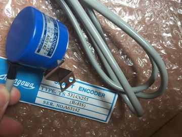
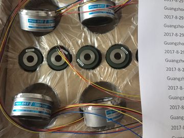
| Brand Name: | Tamagawa |
| Certification: | CE |
| Model Number: | TS2651N111E78 |
| Minimum Order Quantity: | 1pcs |
|---|---|
| Packaging Details: | carton |
| Delivery Time: | in stock |
| Payment Terms: | T/T, Western Union, MoneyGram |
| Supply Ability: | 100pcs/week |
| TAMAGAWA: | TAMAGAWA | Material: | Iron |
|---|---|---|---|
| TS2651N111E78: | TS2651N111E78 | Japan: | Japan |
| Temperature: | 20-90 | Color: | Black |
| Wire: | Wire | Dimension: | 90mm |
| RET_VAL OUT Int Status (condition code) | Word, or DWord) or an array of a bit type. |
| STATE1 InOut Variant Buffer that receives the error status of each module: The data type | Summary bit: Bit 0 =1, if one of the state bits of the I/O module is 1 |
| you use for the STATE parameter can be any bit type (Bool, Byte, | State bit: State of I/O module with slot number n according to |
Guang Zhou Lai Jie Electric Co.,LTD
TS5667N120
TS4127N1017E215
TS1982N126E6
TS3653N44E8
TS3630N1E2
TS5013N89
TS2651N181E78
TS4127N1017E235
TS1982N128E6
8001231S
TS3653N4E12
TS5013N64
TS3630N2E3
TS5016N
TS5000N532
TS4231N6E17
TS1982N53E6
800123-2R
TS3653N14E12
TS5420N60
TS3630N2E4
TS5016N60
TS5000N632
TS4231N6E17
TS1982N56E18
TS3653N58E5
TS5778N155
TS3630N3E5
TS5003N632
TS4244N10E24
TS1982N56E18
the selected MODE. For example, MODE = 2 and bit 3 = 1
means station 3 is faulty.
1 A maximum of 128 bits can be assigned. The number of bits required is dependent on your I/O module usage.
Table 8- 110 Condition codes
RET_VAL ( W#16#...) Description
0 No error
8091 Module identified by LADDR does not exist.
8092 Module identified by LADDR does not address an I/O device.
8093 Invalid data type for STATE parameter: Valid data types are (Bool, Byte, Word, or Dword), or
an array of (Bools, Bytes, Words, or Dwords). ModuleStates instruction not supported by this CPU for this LADDR.
8452 The complete state data is too large for the assigned STATE parameter. The STATE buffer
contains a partial result.
You can use the "GET_DIAG" instruction to read out the diagnostic information of a
hardware object. The hardware object is selected with the LADDR parameter. With the
MODE parameter, you select which diagnostic information is to be read out. Use the MODE parameter to select which diagnostic data is to be
output.
LADDR IN HW_ANY (Word) Hardware ID of the device
RET_VAL OUT Int Status of the instruction
CNT_DIAG OUT UInt Number of output diagnostic details
DIAG InOut Variant Pointer to data area for storage of diagnostic information of the
selected mode
DETAILS InOut Variant Pointer to data area for storage of diagnostic details in accordance
with the selected modeOutput of all supported
diagnostic information for a
module as DWord, where Bit
X=1 indicates that mode X is
supported.
Bit string of the supported
modes as DWord, where Bit
X=1 indicates that mode X
is supported.
0 -
1 Output of the inherent status
of the addressed hardware
object.
Diagnostics status: Output
in accordance with the DIS
structure. (Note: Refer to
the "DIS structure"
information below and
GET_DIAG instruction
example at the end of the
section.)
0 -
2 Output of the status of all
subordinate modules of the
addressed hardware object.
Output of diagnostics datain accordance with the DNN
structure. (Note: Refer tothe "DNN structure"
information below andGET_DIAG instruction
example at the end of thesection.)0 Module status
information inaccordance with the
DiagnosticsDetailsstructure.
DIS structureWith the MODE parameter = 1, the diagnostics information is output in accordance with theDIS structure. The following table shows the meaning of the individual parameter values:able 8- 114 Structure of the Diagnostic Information Source (DIS) Status of the module sub-modules:
Bit 0 to 15: Status message of the module
Bit 16 to 31: Status message of the CPU0 to 2enum)Additional informationBit 0: No additionalinformation Bit 1: Transfer not permitted3 Bit 3 = 1: At least one channel supports qualifiers fordiagnostics.4 Bit 4 = 1: Maintenance required for at least one channel or onecomponent5 Bit 5 = 1:Maintenance demanded for at least one channel or onecomponent6 Bit 6 = 1: Error in at least onechannel or one component7 to 10 -11 to 14 Bit 11 = 1: PNIO - sub-module correctBit 12 = 1: PNIO - Bit 13 = 1: PNIO - incorrect module