|
| Place of Origin: | Japan |
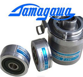
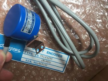
| Brand Name: | Tamagawa |
| Certification: | CE |
| Model Number: | TS5667N420 |
| Minimum Order Quantity: | 1pcs |
|---|---|
| Packaging Details: | carton |
| Delivery Time: | in stock |
| Supply Ability: | 100pcs/week |
| TAMAGAWA: | TAMAGAWA | TS5667N420: | TS5667N420 |
|---|---|---|---|
| Japan: | Japan | Material: | Iron |
| Color: | Black | Temperature: | 20-90 |
| Wire: | Wire |
| convert, math, or PID box to write the desired pulse width to the appropriate Q word. |
Digital I/O points assigned to PWM and PTO cannot be forced |
| configuration ("Output addresses" / "Start address:") as needed to change the pulse width. You use an instruction such as a move, |
The digital I/O points used by the pulse-width modulation (PWM) and pulse-train output |
| You must use the valid range for the Q-word value (percent, thousandths, ten-thousandths, or S7 analog format). |
(PTO) devices are assigned during device configuration. When digital I/O point addresses are assigned to these devices, |
Guang Zhou Lai Jie Electric Co.,LTD
TS5667N120
TS4127N1017E215
TS5667N420
TS3653N58E5
TS5778N155
TS3630N3E5
TS5003N632
TS4244N10E24
TS1982N56E18
800123-R-F
TS3653N65E27
TS5208N23
TS3630N101E2
TS5017N56
TS5005N122
TS4244N3E24
TS1983N146E5
TS3653N81E27
TS2025N471E69
TS3630N102E4
TS5017N60
TS5007N122
TS4502N1000E200
TS1983N146E5
TS3653N78E5
TS2014N181E32
TS3630N22E3
TS5108-N153-5V
TS5007N635
TS4502N1202E200
TS252N30E1
AU6270N103E63
the values of the assigned I/O point addresses cannot be
modified by the Watch table force function. If one of these errors occurs when a code block is executed, the CPU goes to STOP mode unless you use the GetError
or GetErrorID instructions within that code block to create a programmed reaction to the error. Pulse width can be expressed as hundredths of the
cycle time (0 to 100), as thousandths (0 to 1000), as
ten thousandths (0 to 10000), or as S7 analog format.
The pulse width can vary from 0 (no pulse, always off)
to full scale (no pulse, always on). Since the PWM output can be varied from 0 to full scale, it provides a digital output that in
many ways is the same as an analog output. For example, the PWM output can be used to
control the speed of a motor from stop to full speed, or it can be used to control position of a
valve from closed to fully opened.
Two pulse generators are available for controlling high-speed pulse output functions: PWM
and Pulse train output (PTO). PTO is used by the motion control instructions. You can assign
each pulse generator to either PWM or PTO, but not both at the same time.
The two pulse generators are mapped to specific digital outputs as shown in the following
table. You can use onboard CPU outputs, or you can use the optional signal board outputs.
The output point numbers are shown in the following table (assuming the default output
configuration). If you have changed the output point numbering, then the output point
numbers will be those you assigned. Regardless, PTO1/PWM1 uses the first two digital
outputs, and PTO2/PWM2 uses the next two digital outputs, either on the CPU or on the
attached signal board. Note that PWM requires only one output, while PTO can optionally
use two outputs per channel. If an output is not required for a pulse function, it is available
for other uses.When you configure the outputs of the CPU or signal board as pulse generators (for use
with the PWM or motion control instructions), the corresponding outputs addresses (Q0.0,
Q0.1, Q4.0, and Q4.1) are removed from the Q memory and cannot be used for other
purposes in your user program. If your user program writes a value to an output used as a
pulse generator, the CPU does not write that value to the physical output.To prepare for PWM operation, first configure a pulse channel in the device configuration by
selecting the CPU, then Pulse Generator (PTO/PWM), and choose either PWM1 or PWM2.
Enable the pulse generator (check box). If a pulse generator is enabled, a unique default
name is assigned to this particular pulse generator. You can change this name by editing it
in the "Name:" edit box, but it must be a unique name. Names of enabled pulse generators
will become tags in the "constant" tag table, and will be available for use as the PWM
parameter of the CTRL_PWM instruction.
NOTICE
The maximum pulse frequency of the pulse output generators for the digital output is
100 KHz (for the CPU), 20 KHz (for a SB), or 200 KHz (for a high-speed SB). However,
STEP 7 does not alert you when you configure an axis that with a maximum speed or
frequency that exceeds this hardware limitation. This could cause problems with your
application, so always ensure that you do not exceed the maximum pulse frequency of the
hardwareYou have the option to rename the pulse generator, add a comment, and assign parameters
as follows:
● Pulse generator used as follows: PWM or PTO (choose PWM)
● Output source: onboard CPU or SB
● Time base: milliseconds or microseconds
● Pulse width format:
– Hundredths (0 to 100)
– Thousandths (0 to 1000)
– Ten-thousandths (0 to 10000)
– S7 analog format (0 to 27648)
● Cycle time: Enter your cycle time value. This value can only be changed in Device