 |
| Place of Origin: | Japan |
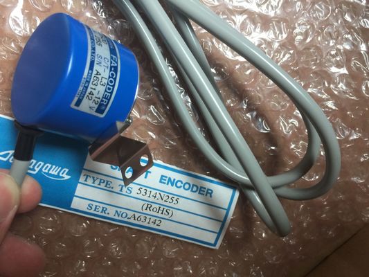
| Brand Name: | Tamagawa |
| Certification: | CE |
| Model Number: | TS5214N8566 |
| Minimum Order Quantity: | 1pcs |
|---|---|
| Packaging Details: | carton |
| Delivery Time: | in stock |
| Payment Terms: | T/T, Western Union, MoneyGram |
| Supply Ability: | 100pcs/week |
| TAMAGAWA: | TAMAGAWA | TS5214N8566: | TS5214N8566 |
|---|---|---|---|
| WIRE: | WIRE | Color: | Black |
| Material: | Iron | Temperature: | 70mm |
| Dimension: | 70mm |
Guang Zhou Lai Jie Electric Co.,LTD
TS5214N8566
TS3617N13E8
TS3617N376
TS3617N381
TS3617N3E9
TS3617N13E9
TS3617N40E3
TS3617N47E4
TS3624N1E1
TS3624N21E1
TS3624N21E2
TS3624N1E2
TS3624N102E4
TS3624N103E5
TS3624N203E5
TS3624N22E4
TS3624N23E5
TS3624N2E3
TS3624N2E4
TS3624N3E5
TS3624N3E6
TS3630N1303E9
![]()
![]()
![]()
![]()
| As each current-count-value-equals-preset-value interrupt event occurs, | nd the cycle is repeated. Since the interrupts occur at a much lower rate than the counting rate of the HSC |
| a new preset is loaded and the next state for the outputs is set. |
precise control of high-speed operations can be implemented with relatively minor impact to the scan cycle of the CPU. |
| When the reset interrupt event occurs, the first preset and the first output states are set, |
he method of interrupt attachment allows each load of a new preset to be performed in a separate interrupt routine for easy state control. (Alternatively, all interrupt events can be processed in a single interrupt routine. |
The digital I/O points used by high-speed counter devices are assigned during device
configuration. When digital I/O point addresses are assigned to these devices, the values of
the assigned I/O point addresses cannot be modified by the force function in a watch table.
When you configure the CPU, you have the option to enable and configure each HSC. The
CPU automatically assigns the input addresses for each HSC according to its configuration.
(Some of the HSCs allow you to select whether to use either the on-board inputs of the CPU
or the inputs of an SB.)
NOTICE
As shown in the following tables, the default assignments for the optional signals for the
different HSCs overlap. For example, the optional external reset for HSC 1 uses the same
input as one of the inputs for HSC 2.
Always ensure that you have configured your HSCs so that any one input is not being used
by two HSCs.
The following table shows the HSC input assignments for both the on-board I/O of the CPU
1211C and an SB. (If the SB has only 2 inputs, only 4.0 and 4.1 inputs are available.)
● For single-phase: C is the Clock input, [d] is the optional direction input, and [R] is an
optional external reset input. (Reset is available only for "Counting" mode.)
● For two-phase: CU is the Clock Up input, CD is the Clock Down input, and [R] is an
optional external reset input. (Reset is available only for "Counting" mode.)
● For AB-phase quadrature: A is the Clock A input, B is the Clock B input, and [R] is an
optional external reset input. (Reset is available only for "Counting" mode.)
Table 9- 6 HSC input assignments for CPU 1211C HSC 1 and HSC 2 can be configured for either the on-board inputs or for an SB.
2 HSC 5 and HSC 6 are available only with an SB. HSC 6 is available only with a 4-input SB.
3 An SB with only 2 digital inputs provides only the 4.0 and 4.1 inputs.
The following table shows the HSC input assignments for both the on-board I/O of the CPU
1212C and an SB. (If the SB has only 2 inputs, only 4.0 and 4.1 inputs are available.)
● For single-phase: C is the Clock input, [d] is the optional direction input, and [R] is an
optional external reset input. (Reset is available only for "Counting" mode.)