|
| Place of Origin: | Japan |
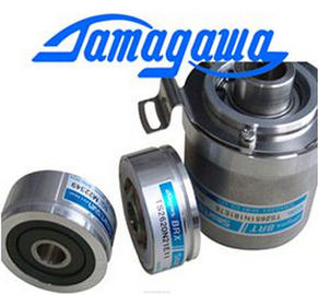
| Brand Name: | Tamagawa |
| Certification: | CE |
| Model Number: | TS2620N21E11 |
| Minimum Order Quantity: | 1pcs |
|---|---|
| Packaging Details: | carton |
| Delivery Time: | in stock |
| Payment Terms: | T/T, Western Union, MoneyGram |
| Supply Ability: | 100pcs/week |
| TAMAGAWA: | TAMAGAWA | TS2620N21E11: | TS2620N21E11 |
|---|---|---|---|
| Material: | Iron | Japan: | Japan |
| Color: | Black | Temperature: | 30-90 |
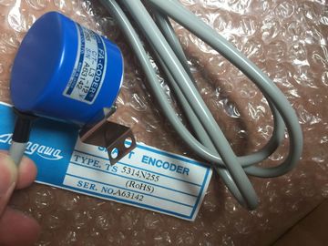
| Wire: | Wire | Dimension: | 80mm |
| (Locate this value on the data sheet or the faceplate of the valve.) Error behavior Defines the behavior of the v |
|
| Sets the minimum pause time for the valve. | |
| If you select to use a substitute position, |
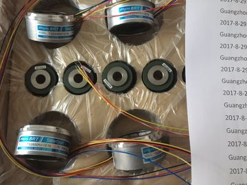
Guang Zhou Lai Jie Electric Co.,LTD
TS5246N160
TS3641N32
TS3641N38
TS3643N2
TS3643N212E5
TS3643N233E8
TS3653N11E2
TS3653N12E5
TS3653N13E8
TS3653N1E1
TS3653N1E2
TS3653N2E4
TS3653N2E5
TS3653N2E6
TS3653N3E7
TS3653N3E8
TS3653N3E9
TS3653N13E9
TS3653N44E8
TS3653N4E12
![]()
![]()
![]()
"High stop" and "Lower limit stop" define the maximum positive position (full-open)
and the maximum negative position (full-closed). "High stop" must be greater than
"Lower limit stop".
? "High limit process value" and "Low limit process value" define the upper and lower
positions of the valve during tuning and automatic mode.
? "FeedbackPER" ("Low" and "High") defines the analog feedback of the valve
position. "FeedbackPER High" must be greater than "FeedbackPER Low".
1 "Scale Position Feedback" is editable only if you enabled "Feedback" in the "Basic" settings.
9.2.7 Commissioning the PID controller
Use the commissioning editor to configure the PID controller for autotuning at startup
and for autotuning during operation. To open the commissioning editor, click the icon
on either the instruction or the project navigator. ? Measurement: To display the setpoint, the
process value (input value) and the output value in a
real-time trend, enter the sample time and click the
"Start" button.
? Tuning mode: To tune the PID loop, select either
"Pretuning" or "Fine tuning" (manual) and click the
"Start" button. The PID controller runs through
multiple phases to calculate system response and
update times. The appropriate tuning parameters are
calculated from these values.
After the completion of the tuning process, you can
store the new parameters by clicking the "Upload PID
parameters" button in the "PID Parameters" section of
the commissioning editor.
If an error occurs during tuning, the output value of the
PID goes to 0. The PID mode then is set to "inactive"
mode. The status indicates the error. Motion control
The CPU provides motion control functionality for the operation of stepper motors and servo
motors with pulse interface. The motion control functionality takes over the control and
monitoring of the drives.
● The "Axis" technology object configures the mechanical drive data, drive interface,
dynamic parameters, and other drive properties.
● You configure the pulse and direction outputs of the CPU for controlling the drive.
● Your user program uses the motion control instructions to control the axis and to initiate
motion tasks.
● Use the PROFINET interface to establish the online connection between the CPU and
the programming device. In addition to the online functions of the CPU, additional
commissioning and diagnostic functions are available for motion control.
Note
Changes that you make to the motion control configuration and download in RUN mode
do not take effect until the CPU transitions from STOP to RUN mode.